ACR-EX-2xxNILCD-I1-C
S0 Pulse Input to NB-IoT Converter with an LCD Display and Integrated Antenna
Quick start guide for S0 pulse input to NB-IoT converter with an LCD display and integrated antenna ACR-EX-2xxNILCD-I1-C.
warning
Beware that the device is intended to be used only with private APN in order to comply with RED-DA EU directive.

| Ordering Code | Network | Protocol | Power Source | Max. Devices |
|---|---|---|---|---|
| ACR-EX-2xxNILCD-I1-C | NB-IoT | S0 pulse counter | C-Cell battery | 1 |
info
For further technical details, check the datasheet for NILCD-I1-C.
Installation Process
1. Unscrew the 4 screws holding the lid, remove it and put it aside.


2. If the box comes with a battery inside, put it outside of the box (for better handling) and insert a SIM card - if it is not pre-inserted.

3. Run the interface cable through the cable gland and connect the conductors to the WAGO connector – each to a single entry. Make sure the contact is long enough (0,5 to 1 cm).

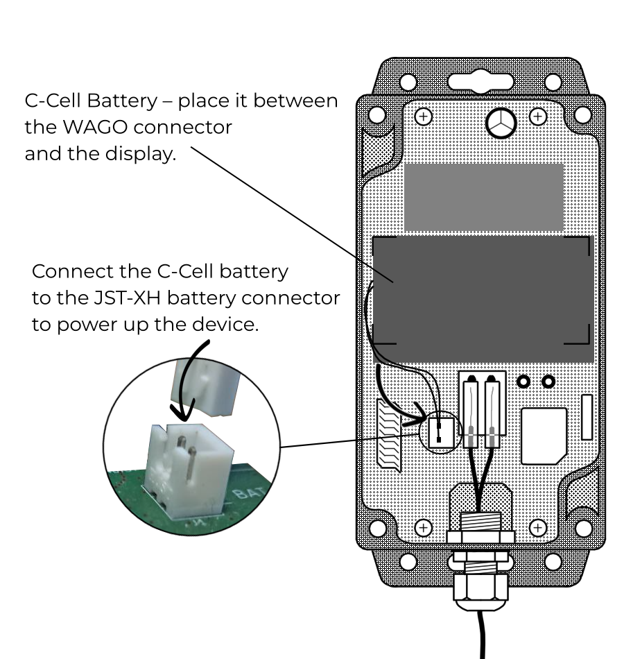
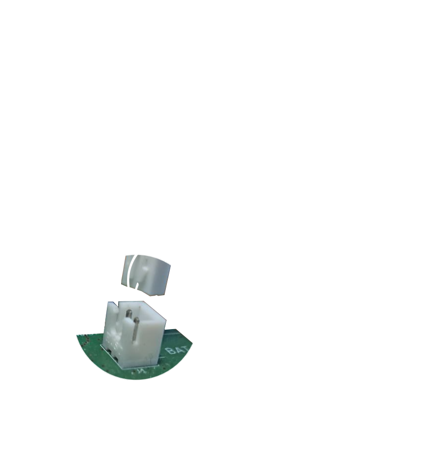
4. Connect the battery to the JST-XH connector – to power up the device – and place it between the display and WAGO connector.
5. Place the lid back on the box, align it and tighten the screws.

6. Secure the device in place with screws and mounting holes or via other means such as cable ties - or in any other way according to your needs.

7. Now you can configure the device via Optical Head - if needed.
For further details, consult either the GUI Tutorial Article or the Configuration section below.
Configuration
ACR-EX GUI is a graphical user interface for ACR-EX devices. It is a tool that allows you to configure and readout your ACR-EX devices.
Requirements
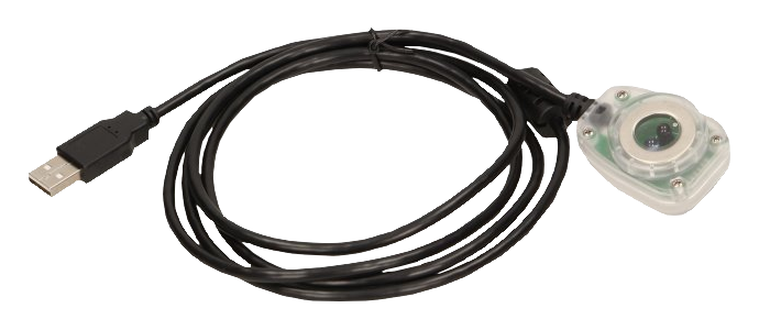
To manage the ACR-EX device you need a Chromium-based browser (Google Chrome is recommended) and an optical probe.
Connecting to the GUI and configuring the device
- Connect the optical probe to the computer via USB port.

- Open the browser and navigate to ACR-EX GUI.
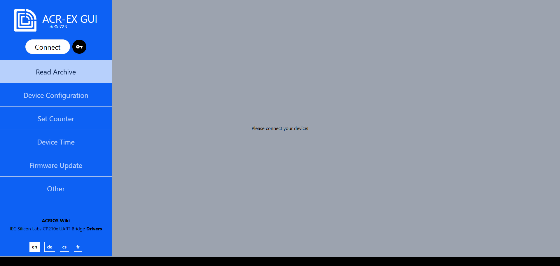
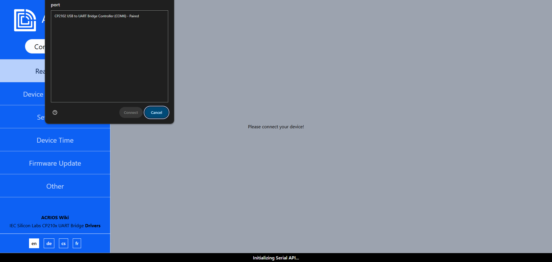
- Click on the Connect button.
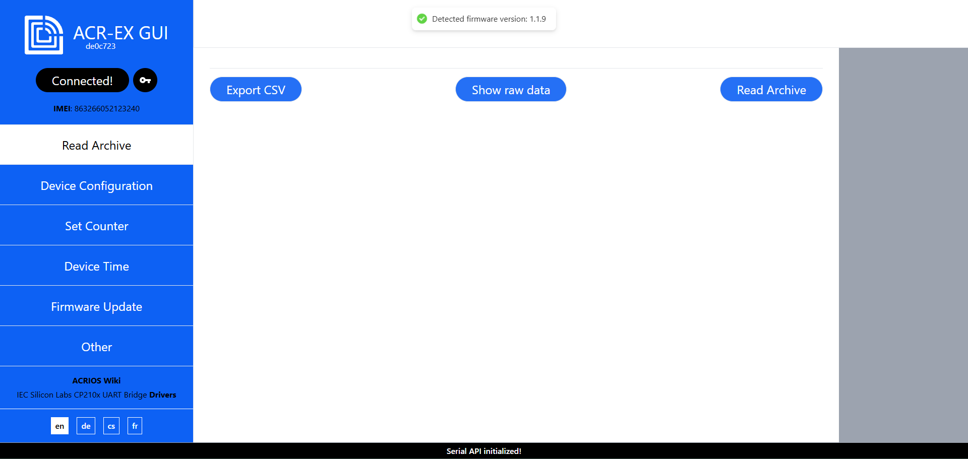
- The optical head should be detected (make sure the driver was installed), select it and click on the Connect.
- If you connected successfully, you should see the following screen.

- Tap the Magnetic Trigger on the side to enter the IEC Mode.

- Place the IEC Head on the top of the Metal Circle to begin a data transfer – both for configuration and data readout.

Showcase GIF
- You can either Load Config From Device or Show Default Values (of configuration).
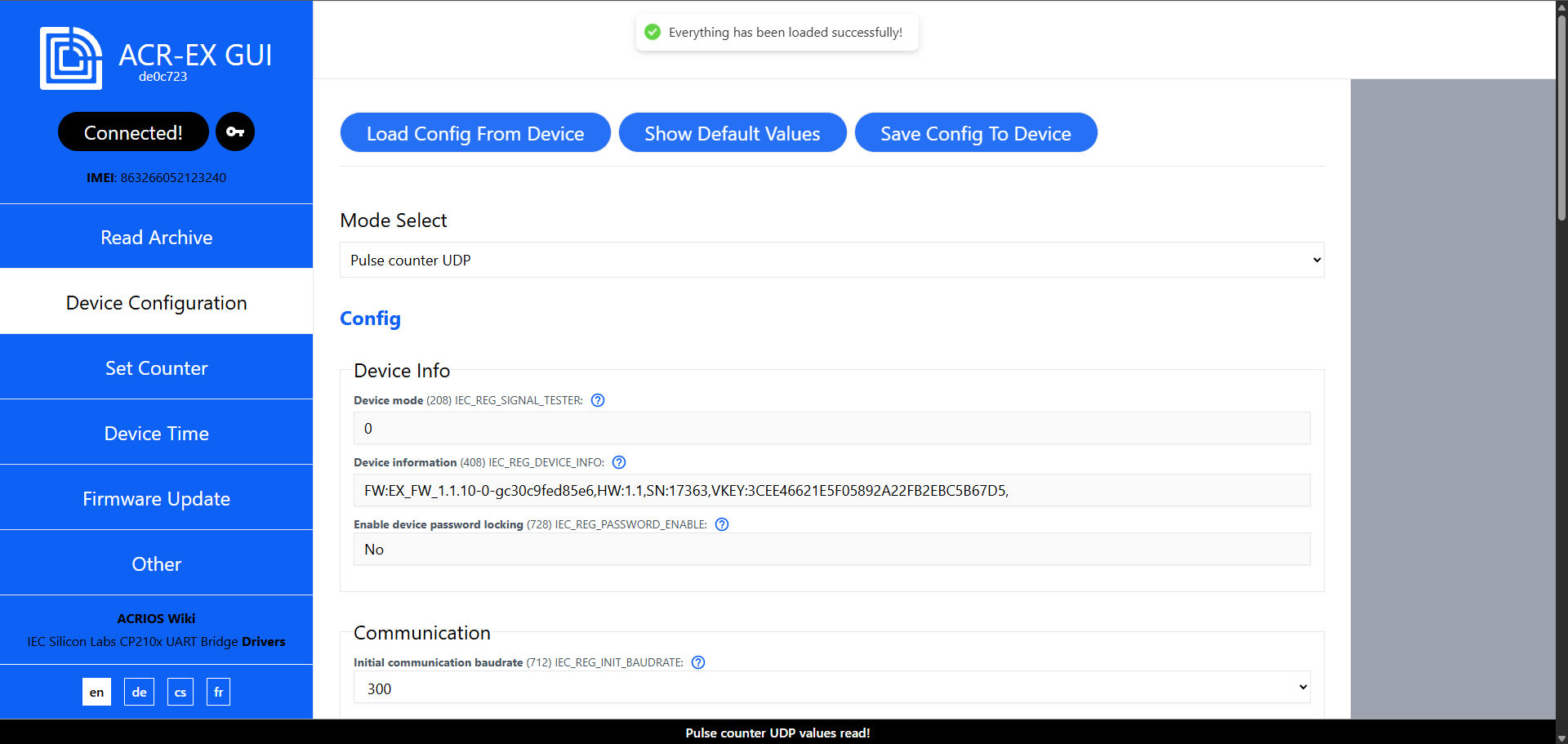
- Configure the device config according to your needs.
- Press Save Config To Device.
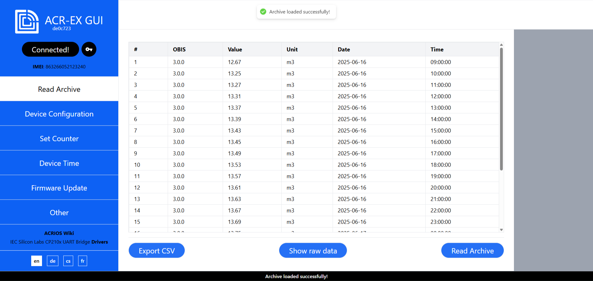
Reading the archive
- After connecting to the device, click on the Read Archive button.

- Click on the Read Archive button.
Setting the counter
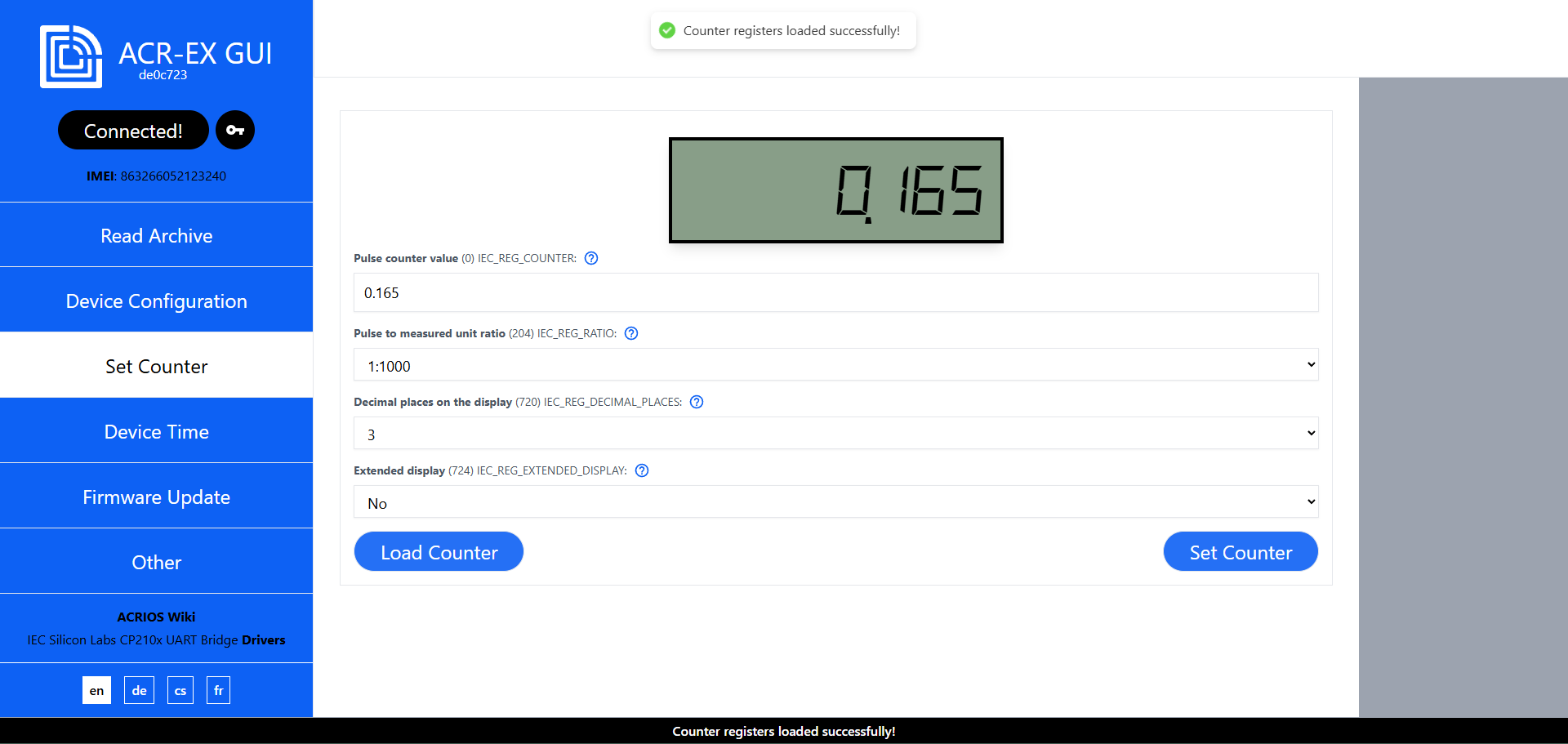
- After connecting to the device, click on the Set Counter button.

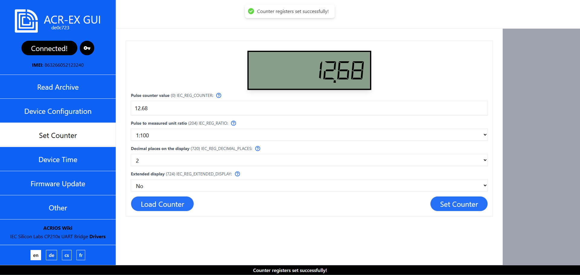
- You can either Load Counter or Set Counter.
- Set the counter value and click on the Set Counter button.
Was anything unclear, missing or hard to understand? Please, contact us at support@acrios.com.
Further information can be found on wiki.acrios.com.