Modbus with a device library - LoRaWAN
Integration manual for the ACRIOS Systems converters ACR-CV-1xxL-R12-D and ACR-CV-1xxL-R12-EAC using LoRaWAN, possible to use also with versions ACR-CV-1xxL-R-D and ACR-CV-1xxL-R-EAC.
Introduction
This is the documentation needed for the ACRIOS Systems Modbus to LoRaWAN concentrator. The documentation refers to the default Lua script used and covers possible configuration options.
Please note, that the standard Lua script is not used here. If you wish to obtain the script, please, contact us at support@acrios.com.
Typical Use-Case
Modbus energy meters are often deployed in large numbers in many urban areas. The lack of standardization poses a significant challenge, where each Modbus meter requires separate, lengthy implementation, leading to inefficiencies, errors, and increased costs. Whereas manual readings often suffer from inaccuracies and delays, our Modbus to LoRaWAN Converter is an ideal solution to seamlessly integrate all the varied Modbus meters into a unified, remote monitoring system.
Scenario:
Property managers, utility companies, and industrial facility supervisors often have to manage multiple of Modbus meters. It can become difficult to gather all the data due to lack of standardization. Therefore, an automated and easy to manage solution would resolve such issue immediately.
Solution:
Our Modbus to LoRaWAN Converter allows for standardization for diverse portfolio of Modbus meters. Its implementation allows for an easy customization and swift over-the-air configuration. Our converter allows for a smooth transition from manual configuration to a unified, automated system.
Benefits:
- Streamlined Integration: Overcoming the challenges of non-standardized Modbus communication, our converter unifies the integration process, saving time and effort.
- Error Reduction: By eliminating manual device on-site configuration and the need for separate meter implementations, the converter significantly reduces the margin of error, ensuring accurate readings.
- Reliable Communication: The external antenna ensures reliable signal propagation, maintaining consistent communication even in complex architectural environments.
- Future-Proof Solution: The converter’s adaptability ensures it can accommodate new Modbus meters seamlessly, making it a future-proof investment.
Converter Integration
Functions
The device contains following functions:
- Payload length of at most 51 B
- Acknowledged messages with up to 8 retransmission. If there is no ACK ⇒ retransmission triggers.
- Setup library containing:
- Baud rate
- Stop bits
- Parity
- Function code
- AUX power supply 12 V DC - only for “R12” versions
- How long the device has to be powered-on (measured in seconds)
- Registers list
- Remote configuration
- Which sensor from library we want to read on which address and how often
- Device wake-up interval
- Remote library modification
- Time synchronization over MAC layer
- Local history of unsent frames
Time Synchronization
Time synchronization occurs automatically upon device startup. This functionality is compatible exclusively with LoRaWAN 1.0.3 and later versions, and its functionality depends on the support by network server.
Out of the Box Behavior
When the device is powered up, the bootloader starts. The bootloader is responsible for the correct launch of the application firmware and also allows OTA firmware update. It runs for approximately 3 minutes (the LED will be flashing during this time). It can be also skipped by pressing the button.
At the end of the bootloader, the device skips to the application part of the firmware, beginning with the initialization of all the necessary peripherals and loading the Lua script stored in the memory. With the Lua script initialization, the setup configuration is loaded (referred to as the "Setup library"), which is based on the specifications outlined in the Lua script header.
This is how it looks on the first Startup():
Initialization looks as following:
[     1161][SYS]: console ready
[     1164][MEM]: init done, heap 48992 bytes, bss 11640 bytes, stack 4128 bytes
[     3752][SYS]: Reset Reason: BOR reset
[     3756][SYS]: FW version: CV_FW_2.13.1
[     3762][SYS]: Model: ACR_CV_101L_R12_D
[     3767][SYS]: SN: 1111
[     3769][SYS]: date / time - 2016/01/01 / 00:00:02
[     3775][SYS]: build date / time - Nov 23 2023 / 23:23:23
Loading the Lua script and starting the OnStartup() section:
[     8379][STDOUT]: version: 1
[     8427][STDOUT]: Create setup table
[     8461][STDOUT]: Load setup library to eeprom and table
[     8511][STDOUT]: Add index lib 1 to eeprom

00 : 01 02 01 08 02 03 02 40 00 00 00 0B B8 00 00 03
10 : E8

[     8684][STDOUT]: Add index lib 2 to eeprom

00 : 02 02 01 08 02 03 02 50 00 00 00 0B B8 00 00 03
10 : E8

[     8857][STDOUT]: Add index lib 3 to eeprom

00 : 03 02 01 08 02 03 02 50 08 00 00 0B B8 00 00 03
10 : E8

[     9013][STDOUT]: No History
OnWake() function:
[     9229][LORA]: Time sync requested
[     9234][LORAMAC]:  # === MLME-Request == #
[     9239][LORAMAC]: #            MLME_DEVICE_TIME           #
[     9246][LORAMAC]: # ===== #
[     9250][LORAMAC]: STATUS      : OK
[     9258][HWAPI_COMMON]: Cannot get used count in non-existent table ID 2
[     9283][HWAPI_COMMON]: Cannot get used count in non-existent table ID 2
[     9309][LORA]: Force confirmed message after join!
[     9314][LORA]: Not joined, join and continue.
[     9345][LORAMAC]:  # === MLME-Request == #
[     9351][LORAMAC]: #               MLME_JOIN               #
[     9358][LORAMAC]: # ===== #
[     9362][LORAMAC]: STATUS      : OK
[    14610][LORAMAC]:  # === MLME-Confirm == #
[    14615][LORAMAC]: STATUS      : OK
[    14620][LORAMAC]: # ===   JOINED     == #
[    14625][LORAMAC]:  OTAA
[    14628][LORAMAC]: DevAddr     :  00BF3DF8
[    14634][LORAMAC]:
[    14637][LORAMAC]: DATA RATE   : DR_4
[    14645][LORAMAC]:  # == CTXS STORED == #
[    14650][LORAMAC]: Size        : 1112
[    14746][LORAMAC]:  # === MCPS-Request == #
[    14751][LORAMAC]: #            MCPS_CONFIRMED             #
[    14759][LORAMAC]: # ===== #
[    14762][LORAMAC]: STATUS      : OK
[    19958][LORAMAC]:  # === MCPS-Confirm == #
[    19963][LORAMAC]: STATUS      : OK
[    19968][LORAMAC]:  # =   UPLINK FRAME        1   = #
[    19974][LORAMAC]:
[    19977][LORAMAC]: CLASS       : A
[    19982][LORAMAC]:
[    19984][LORAMAC]: TX PORT     : 1
[    19989][LORAMAC]: TX DATA     : CONFIRMED - ACK
[    19995][LORAMAC]: FF FF
[    19998][LORAMAC]:
[    20001][LORAMAC]: DATA RATE   : DR_4
[    20006][LORAMAC]: U/L FREQ    : 868100000
[    20011][LORAMAC]: TX POWER    : 0
[    20016][LORAMAC]: CHANNEL MASK: 00FF
[    20020][LORAMAC]:
[    20023][LORAMAC]:  # === MLME-Confirm == #
[    20029][LORAMAC]: STATUS      : OK
[    20033][LORAMAC]:  # == MCPS-Indication == #
[    20039][LORAMAC]: STATUS      : OK
[    20043][LORAMAC]:  # =  DOWNLINK FRAME        0  = #
[    20050][LORAMAC]: RX WINDOW   : 1
[    20054][LORAMAC]: RX PORT     : 0
[    20059][LORAMAC]:
[    20062][LORAMAC]: DATA RATE   : DR_4
[    20066][LORAMAC]: RX RSSI     : -38
[    20071][LORAMAC]: RX SNR      : 13
[    20076][LORAMAC]:
[    20078][LORA]: Time sync received
[    20086][LORAMAC]:  # == CTXS STORED == #
[    20091][LORAMAC]: Size        : 472
[    20621][LORA]: Continue unconfirmed msg.
[    20652][STDOUT]: no downlink received
[    20699][STDOUT]: sleep for:1
[    20712][SYS]: entering sleep mode
First, it adds a request for the next LoRa message to request a time synchronization from a network server. Then it checks if the Modbus ID table has any configuration stored followed by a 2-byte "Empty configuration message" represented with 0xFF 0xFF. During the sending procedure, the firmware checks if the device is connected to the Lora network server, if not (which is the case above) it will proceed with the join request. If the join request is successful, the device sends the message and goes to sleep mode.
Upon receiving a valid configuration frame containing Setup ID, Modbus address, and wake-up period, the device stores this information in its EEPROM. From this point forward, every time the device wakes up, it will initiate a Modbus request to the Modbus ID that has been configured.
For further details, please refer to the Communication Protocol Description or Example Application sections below.
Hardware Used
- ACR-CV-1xxL-R-D - Modbus to LoRaWAN converter, battery powered.
- ACR-CV-1xxL-R-EAC - Modbus to LoRaWAN converter, externally powered.
- ACR-CV-1xxL-R12-D - Modbus to LoRaWAN converter, battery powered with AUX power supply 12V DC for connected sensors.
- ACR-CV-1xxL-R12-EAC - Modbus to LoRaWAN converter, externally powered with AUX power supply 12V DC for connected sensors.
The converter allows you to connect any meter or other device equipped with an Modbus communication. Depending on the hardware version you can also connect sensors requiring power supply of 12 V DC.
Hardware Limitations
- Hardware allows you to connect up to 96 UL.
- For the versions with external power supply for the sensor (”R12” versions), the maximum recommended current is:
| Version | Recommended Max Current |
|---|---|
| ACR-CV-1xxL-R12-D2 | 47,3 mA |
| ACR-CV-1xxL-R12-D | 21 mA |
| ACR-CV-1xxL-R12-EAC | 100 mA |
- The typical battery life time for the versions without auxiliary power supply for the sensors - ACR-CV-1xxL-R-D - is:
| Reading and Sending Interval | Estimated Battery Lifetime |
|---|---|
| 15 min | 16 years* |
| 30 min | 18 years* |
| 60 min | 23 years* |
Note that due to battery degradation, we suggest to limit the application of a single battery to ten years at most.
Please note that these are rough estimates because the battery lifetime is directly related to the number of connected sensors, its power consumption and required initialization delay.
Application Limitations
- From the nature of LoRaWAN communication it might be needed to shorten the payload as you can transfer up to 51 bytes with SF12.
- From the nature of LoRaWAN communication it is needed to be cautious when connecting multiple sensors with frequent readings as the communication might be limited by Duty cycle.
Communication Protocol Description
Setup Library
Below is the structure of the Setup library with the size of its variables.
| Position | Description | Size |
|---|---|---|
| 1 | SetupID | 1B |
| 2 | Baudrate | 1B |
| 3 | Stop Bits | 1B |
| 4 | Data Bits | 1B |
| 5 | Parity | 1B |
| 6 | Function Code | 1B |
| 7 | Register count | 1B |
| 8 | Register Address | 2B |
| 9 | RXTimeout | 4B |
| 10 | Pre-Heat Time | 4B |
The SetupID functions as an identifier for configurations stored in the Setup table. The Setup library enables reading or writing of registers for meters or sensors. This flexibility allows the use of one or more registers for one or more devices. For example, when working with a single meter and the requirement to access non-consecutive registers (with multiple registers in between and no necessity to read all registers), the Setup library supports the use of multiple configurations.
Setup library should be sorted with the sensors starting from the lowest "Pre-Heat Time" and ending with the highest. I.e. the lowest index of the table has the lowest "Pre-Heat Time". This way it reduces the consumption of the battery.
Here is an example:
lib[1] = pack.pack("b7>h>i2",1,6,1,8,0,3,1,0,300,0)
lib[2] = pack.pack("b7>h>i2",2,6,1,8,0,3,1,0,100,2500)
lib[3] = pack.pack("b7>h>i2",3,1,1,8,0,3,2,0,100,3000)
lib[4] = pack.pack("b7>h>i2",4,1,1,8,0,3,1,0,1000,90000)
If the Setup library section of EEPROM is empty, the device loads Setup library defined in the script. Further changes made by the LoRaWAN downlink commands are also reflected in the EEPROM where it is permanently stored.
Modbus ID Library
The following table describes the structure of the Modbus ID library:
| Position | 1 | 2 | 3 |
|---|---|---|---|
| Description | SetupID | Modbus Address | Wake-Up Period |
| Size | 1B | 1B | 2B |
The Modbus ID library is empty until the configuration is received through LoRaWAN downlinks.
Commands
Add configuration into the Modbus ID library (01)
This command is used to store the configuration in both temporary table and EEPROM. Thanks to this, even if the device restarts, the configuration is stored permanently.
Downlink
| Position | 1 | 2 | 3 | 4 |
|---|---|---|---|---|
| Description | CMD | SetupID | Modbus Address | Wake-Up Period |
| Size | 1B | 1B | 1B | 2B |
| Downlink Example | 0x01 | 0x02 | 0x01 | 0x00 0x02 |
Uplink Response
| Position | 1 |
|---|---|
| Uplink response | 0x01 |
| Size | 1B |
Add Sensor Configuration to Library (02)
Command 0x02 is used to add a sensor into the Setup library mentioned above. Below is an example:
Downlink
| Position | Description | Size | Downlink Example |
|---|---|---|---|
| 1 | CMD | 1B | 0x02 |
| 2 | SetupID | 1B | 0x05 |
| 3 | Baudrate | 1B | 0x01 |
| 4 | Stop Bits | 1B | 0x01 |
| 5 | Data Bits | 1B | 0x08 |
| 6 | Parity | 1B | 0x00 |
| 7 | Function Code | 1B | 0x03 |
| 8 | Register count | 1B | 0x01 |
| 9 | Register Address | 2B | 0x00 0x00 |
| 10 | RXTimeout | 4B | 0x00 0x00 0x00 0x64 |
| 11 | Pre-Heat Time | 4B | 0x00 0x00 0x00 0x64 |
Uplink Response
| Position | 1 |
|---|---|
| Uplink response | 0x02 |
| Size | 1B |
Modify the Index in the Table and EEPROM (03)
Command 03 manipulates with the Table Index for given Table ID. It can change the indexes of given table and also remove them. Removal is possible only in such case when it is the last index in the table.
Setup Table ID = 1
Configuration Table ID = 2
Downlink #1 (Setup Table)
| Position | Description | Size | Downlink Example |
|---|---|---|---|
| 1 | CMD | 1B | 0x03 |
| 2 | Table ID | 1B | 0x01 |
| 3 | Table Index | 1B | 0x01 |
| 4 | SetupID | 1B | 0x05 |
| 5 | Baudrate | 1B | 0x01 |
| 6 | Stop Bits | 1B | 0x01 |
| 7 | Data Bits | 1B | 0x08 |
| 8 | Parity | 1B | 0x00 |
| 9 | Function Code | 1B | 0x03 |
| 10 | Register count | 1B | 0x01 |
| 11 | Register Address | 2B | 0x00 0x00 |
| 12 | RXTimeout | 4B | 0x00 0x00 0x00 0x64 |
| 13 | Pre-Heat Time | 4B | 0x00 0x00 0x00 0x64 |
Downlink #2 (Modbus ID Table)
| Position | Description | Size | Downlink Example |
|---|---|---|---|
| 1 | CMD | 1B | 0x03 |
| 2 | Table ID | 1B | 0x02 |
| 3 | Table Index | 1B | 0x01 |
| 4 | SetupID | 1B | 0x02 |
| 5 | Modbus Address | 1B | 0x01 |
| 6 | Wake-Up Period | 2B | 0x00 0x02 |
Downlink #3 (Remove Table Index)
This command uses a second command (CMD 2 = 0xFF) to remove index for given Table ID and Table Index. Removal is possible only in such case when it is the last index in the table.
| Position | 1 | 2 | 3 | 4 |
|---|---|---|---|---|
| Description | CMD | Table ID | Table Index | CMD 2 |
| Size | 1B | 1B | 1B | 1B |
| Downlink Example | 0x03 | 0x02 | 0x02 | 0xFF |
Uplink Response
| Position | 1 |
|---|---|
| Uplink response | 0x03 |
| Size | 1B |
Null History Counter (04)
Command 04 removes the history of sent messages stored in the EEPROM.
Downlink
| Position | 1 |
|---|---|
| Description | CMD |
| Size | 1B |
| Downlink Example | 0x04 |
Uplink Response
| Position | 1 |
|---|---|
| Uplink response | 0x04 |
| Size | 1B |
Execute Single Modbus Request (05)
Command 05 allows to execute a Modbus request without storing it into the table or EEPROM.
Downlink
| Position | Description | Size | Downlink Example |
|---|---|---|---|
| 1 | CMD | 1B | 0x05 |
| 2 | Modbus Address | 1B | 0x01 |
| 3 | Pre-Heat Time | 4B | 0x00 0x00 0x00 0x64 |
| 4 | SetupID | 1B | 0x05 |
| 5 | Baudrate | 1B | 0x01 |
| 6 | Stop Bits | 1B | 0x01 |
| 7 | Data Bits | 1B | 0x08 |
| 8 | Parity | 1B | 0x00 |
| 9 | Function Code | 1B | 0x03 |
| 10 | Register count | 1B | 0x01 |
| 11 | Register Address | 2B | 0x00 0x00 |
| 12 | RXTimeout | 4B | 0x00 0x00 0x00 0x64 |
Uplink Response
| Position | 1 |
|---|---|
| Uplink response | 0x05 |
| Size | 1B |
Local History of Unsent Frames
If the device detects the message was not successfully sent, It will store the message with a UNIX 4B (big-endian) timestamp.
The history is accessible during the startup of the device. It will print out a message “Press button in next 20s to get the history” and if the button is pressed, it will print out all the history stored in the memory. If needed, the history can be cleared using the CMD 04 (mentioned above).
Here is an example of what such printout could look like:
[STDOUT]: Press button in next 20s to get the history
	00 : 65 67 3D FD 02 01 43 69 00 00
	00 : 65 67 3E 41 01 01 17 09 10 95
	00 : 65 67 3E 4B 02 01 43 69 00 00
	00 : 65 67 3E 8E 01 01 17 09 10 95
	00 : 65 67 3E 98 02 01 43 69 00 00
As you may have noticed in the example above, the payload has an extra four bytes. These are timestamps associated with given data.
If we take for example the one from the first message -
65 67 3D FDand convert it from big endian hex to uint32, the result is 1701264893. Which when converted from Unix to UTC is 11/29/2023 @ 1:59pm.
Example Application with Inepro PRO1-Mod
The example bellow uses Initial Setup Library and configures reading for the Inepro PRO1-Mod meter. You can find examples of the configuration messages sent by network server (as downlink) to configure the device.
Setup Library is loaded during the startup process and also stored in EEPROM. The library above contains Modbus configuration to read the Inepro meter with specified registers. The “preheat time” is not needed because the voltage source is not used to power the meter, it is only used as demonstration of its functionality.
Device used: Inepro PRO1-Mod
Initial Setup Library:
-- [Setup ID][Baudrate index from the list][Stop Bits][Data Bits][Parity][Function Code]
-- [Register count][Register Address][RXTimeout][Pre Heat Time]

lib[1] = pack.pack("b7>h>i2",1,2,1,8,2,3,2,0x4000,3000,1000) -- 0x4000 = Read serial number
lib[2] = pack.pack("b7>h>i2",2,2,1,8,2,3,2,0x5000,3000,1000) -- 0x5000 = Read voltage
lib[3] = pack.pack("b7>h>i2",3,2,1,8,2,3,2,0x5008,3000,1000) -- 0x5008 = Read grid frequency
Please note that one line in library can contain only one register from one device. In case you would like to read 3 registers from 1 device, the library will contain one line for each register.
Here is the serial line output during the setup library initialization.
[     8427][STDOUT]: Create setup table
[     8461][STDOUT]: Load setup library to eeprom and table
[     8511][STDOUT]: Add index lib 1 to eeprom

00 : 01 02 01 08 02 03 02 40 00 00 00 0B B8 00 00 03
10 : E8

[     8684][STDOUT]: Add index lib 2 to eeprom

00 : 02 02 01 08 02 03 02 50 00 00 00 0B B8 00 00 03
10 : E8

[     8857][STDOUT]: Add index lib 3 to eeprom

00 : 03 02 01 08 02 03 02 50 08 00 00 0B B8 00 00 03
10 : E8
Now the device is sending the 0xFF 0xFF message to the network server asking for configuration every minute:
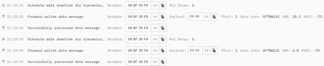
Downlink Configuration - Reading of the Meter from Library
Using the Downlink the Modbus ID library can be configured to use a specific Setup ID to read a given Modbus address for a defined period of time. For example with these messages:
01 01 01 00 01= Use 01 Setup ID configuration with 01 Modbus Address (the address of the meter) every 1 minute01 02 01 00 01= Use 02 Setup ID configuration with 01 Modbus Address (the address of the meter) every 1 minute01 03 01 00 02= Use 03 Setup ID configuration with 01 Modbus Address (the address of the meter) every 2 minutes
This is a scheduling of the downlink, the device receives its configuration:
[LORAMAC]:  # == CTXS STORED == #
[LORAMAC]: Size        : 88

	00 : 01 01 01 00 01
[HWAPI_COMMON]: Cannot get used count in non-existent table ID 2
[STDOUT]: Create new table
Then it sends a confirmation message - 01 - and with the next wake up, requests the data from Inepro meter:
[SYS]: exiting sleep mode
[STDOUT]: Sensor Settings :

	00 : 01 02 01 08 02 03 02 40 00 00 00 0B B8 00 00 03
	10 : E8
[STDOUT]: Address: 1	 Preheat:1000
[STDOUT]: received:

	00 : 17 09 10 95
The device sends the data to the network server 01 01 17 09 10 95.
Scheduling the next dowlink with a second command:
[LORAMAC]:  # == CTXS STORED == #
[LORAMAC]: Size        : 88

	00 : 01 02 01 00 01
[LORAMAC]:  # === MCPS-Request == #
[LORAMAC]: #            MCPS_CONFIRMED             #
The device stores the configuration and sends a confirmation message - 01.
With the next wakeup it reads a voltage value:
[STDOUT]: Sensor Settings :

	00 : 02 02 01 08 02 03 02 50 00 00 00 0B B8 00 00 03
	10 : E8
[STDOUT]: Address: 1	 Preheat:0
[STDOUT]: received:

	00 : 43 68 4C CD
Since the second reading is more than 1000 ms later (the first time preheat time applied on the address 0x4000), the device skips and reads the data immediately. The result here is 0x43684CCD = 232.3 V (converted from hexadecimal float to decimal).
The network server receives 02 01 43 69 00 00.
With the third downlink command scheduled and confirmed - 01.
The device reads all 3 addresses, except with a difference, the third is requested only one in two minutes.
Below is a compressed version highlighting only the Modbus communication controlled by the configuration process explained above.
[STDOUT]: Sensor Settings :
	00 : 01 02 01 08 02 03 02 40 00 00 00 0B B8 00 00 03
	10 : E8
[STDOUT]: Address: 1	 Preheat:1000
[STDOUT]: received:
	00 : 17 09 10 95
[STDOUT]: Sensor Settings :
	00 : 02 02 01 08 02 03 02 50 00 00 00 0B B8 00 00 03
	10 : E8
[STDOUT]: Address: 1	 Preheat:0
[STDOUT]: received:
	00 : 43 67 CC CD
[STDOUT]: Sensor Settings :
	00 : 03 02 01 08 02 03 02 50 08 00 00 0B B8 00 00 03
	10 : E8
[STDOUT]: Address: 1	 Preheat:0
[STDOUT]: received:
	00 : 42 48 0A 3D
The frequency value is 50.01 Hz (42 48 0A 3D converted from hexadecimal float to decimal).
As described in the Commands section above, the table can me manipulated using the downlink messages.
For example by scheduling the following downlink - 03 02 01 01 0A 00 01, the device changes the Modbus configuration in Modbus ID table (in this case it changes only the Modbus ID to 10 instead of 1) leading to the device not being able to receive a response from the meter.
If the device receives no response from the meter, it sends two bytes (Setup ID and Modbus ID).
Which means would to lead to a response 01 0A in the case above.
Troubleshooting & FAQ
The device is not connecting to the Network Server
- Please check if the inserted keys are correct, make sure the device is configured in OTAA and that the AppEUI is not required. In case AppEUI is required, please use the same “0” - 00 00 00 00 00 00 00 00 00 00 00 00 00 00 00 00.
The device did not receive any response from the meter
- Please check if the Modbus configuration is correct - baudrate and parity. Further make sure electrical connection is done properly. You can also try to change parameter “preheat time” to a larger value because some meters may require up to six seconds (6000 ms). Make sure that only one device is connected without any prior changes to configuration.
The device is not connecting to the GUI
- Please, make sure to use a Chromium based browser, we strongly recommend to use Google Chrome (other Chromium based browsers still may cause unexpected issues). Make also sure that the serial line is not opened on any other serial line monitor.
The device has connected, the Lua script was uploaded but it is not possible to connect anymore
- Make sure the battery has been disconnected for a longer period of time to discharge the capacitor or alternatively short the battery pins on the PCB. Connect the two metal pins in the battery connector on the PCB with something conductive (tip of screw driver, paper clip, tip of a pen etc.). The device can connect only when in bootloader or when it is sleeping. If the device is in the application Lua script and currently running, it will not connect.
Where do I configure the Lua script?
- Please, visit: gui.acrios.com. Make sure to use a Chromium based browser, we strongly recommend to use Google Chrome.
Where can I see a data or serial line log?
- You can check any serial line monitor such as PuTTy or Termite. Please, make sure the serial line monitor configuration is - baud rate: 115 200, data bits: 8, stop bits: 1, parity: none.