M-Bus to Wireless M-Bus
Integration manual for the ACRIOS Systems converter ACR-CV-1xxL-M-D used to convert M-Bus to wireless M-Bus (using LoRaWAN model).
Introduction
This is an integration manual for the ACRIOS Systems converter using the following Lua script configuration: ACR_CV_101L_M_X_wmbusBridge.lua. The converter is used to retrofit existing meters with M-Bus communication to wireless M-Bus.
Typical Use-Case
Efficient monitoring and management of heat meters plays a crucial role in optimization of energy consumption and overall operational effectiveness in the realm of district heating stations. The integration of the M-Bus to wireless M-Bus converter presents a streamlined solution that allows for quick deployment and seamless connectivity for heat meter data, ensuring real-time insights and efficient control.
Scenario:
Imagine a district heating station serving a residential complex. This facility relies on a network of heat meters installed within individual apartments to monitor heat consumption accurately. The challenge is to efficiently collect and transmit this consumption data to a central management system for billing, monitoring, and maintenance purposes.
Solution:
The M-Bus to wireless M-Bus converter provides a perfect plug-and-play solution to address this challenge.
Benefits:
- Time and Cost Savings: The quick installation process eliminates extensive configuration and wiring efforts, reducing installation time and associated costs.
- Seamless Integration: The plug-and-play nature of the solution simplifies the integration of heat meters into the district heating network, minimizing disruption to residents.
- Reliable Communication: The external antenna ensures reliable signal propagation, maintaining consistent communication even in complex urban environments.
- Real-Time Insights: The solution provides real-time heat consumption data, enabling accurate billing and informed decision-making for energy optimization.
What Is M-Bus?
M-Bus (Meter-Bus) is a European standard (EN 13757-2 physical and link layer, EN 13757-3 application layer) for the remote reading of water meter, gas or electricity meters. M-Bus is also usable for other types of consumption meters. The M-Bus interface is made for communication on two wires, making it cost-effective. A radio variant of M-Bus (Wireless M-Bus) is also specified in EN 13757-4.
Data on the M-Bus is transferred in telegrams which consist of one or more frames, there must not be any pauses within telegrams, not even after stop bits. M-Bus uses four different telegram formats with following structures:
| Single Character | Short Frame | Control Frame | Long Frame |
|---|---|---|---|
| E5h | Start 10h | Start 68h | Start 68h |
| C Field | L Field = 3 | L Field | |
| A Field | L Field = 3 | L Field | |
| Check Sum | Start 68h | Start 68h | |
| Stop 16h | C Field | C Field | |
| A Field | A Field | ||
| CI Field | CI Field | ||
| Check Sum | User Data (0-252 Byte) | ||
| Stop 16h | Check Sum | ||
| Stop 16h |
❗ When communicating with more meters on the same M-Bus line, it is crucial to provide each slave unit with individual address (A Field). Meter can be addressed by its primary address or by its secondary address.
Primary Addressing:
| Address | Function |
|---|---|
| 0 | Factory default address. |
| 1-250 | Addresses that can be assigned to slaves. (Primary addresses) |
| 251-252 | Reserved for future use. |
| 253 | Indicates that addressing is performed at the network layer instead. (Secondary addressing procedure) |
| 254 | Broadcast, meters reply with their addresses. (Causes collision, test purposes only.) |
| 255 | Broadcast, meters do not reply. |
The secondary address consists of 4 parts:
- 4 bytes being the device ID (serial number)
- 2 bytes being the manufacturer’s identifier
- 1 byte being the device version
- 1 byte being the device media
The benefit of secondary addressing is that there is no need to reconfigure meter’s primary addresses and the installation can be navigated only by modifying the converters’ addressing mechanism.
Converter Integration
Functions
- Configurable M-Bus payload encryption key (default key: internal secret key)
- Configurable initial M-Bus delay (default delay: 5 000 ms)
- Configurable M-Bus parameters
- Configurable VIF DIF filtering
- Configurable wireless M-Bus transmission period of M-Bus readout data (default period: 3 minutes)
- Configurable M-Bus reading period (default period: 6 hours [every 120th transmission of wireless M-Bus is being read: 3 minutes times 120 is 6 hours])
Out of the Box Behavior
After connecting the meter to the converter, the device sends a broadcast query by default to address 254 and the received data are encrypted. Wireless M-Bus payload is assembled and corresponding wireless M-Bus frame is transmitted in T1 mode every three minutes. Encryption uses AES128 in CTR mode.
If the meter is not responding, empty payload is transmitted consisting only of 2F 2F sequence for decryption verification, if the M-Bus device stops responding, the last read-out data is sent without refreshing it.
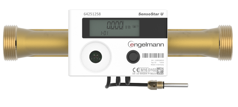
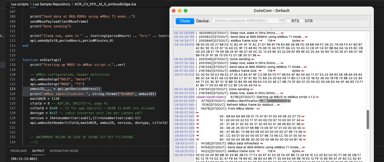
Read-Out Example Using Engelmann SensoStar U
From M-Bus meter
00 : 68 B3 B3 68 08 00 72 98 53 85 30 C5 14 00 0A 8D
10 : 10 00 00 04 78 E6 D0 D6 01 04 06 00 00 00 00 04
20 : 13 00 00 00 00 04 2B 00 00 00 00 14 2B 00 00 00
30 : 00 04 3B 00 00 00 00 14 3B 00 00 00 00 02 5B 18
40 : 00 02 5F 18 00 02 61 C9 FF 02 23 B9 00 04 6D 08
50 : 2A FC 28 44 06 00 00 00 00 44 13 00 00 00 00 42
60 : 6C 00 00 01 FD 17 10 03 FD 0C 05 00 00 84 20 06
70 : 00 00 00 00 C4 20 06 00 00 00 00 84 30 06 00 00
80 : 00 00 C4 30 06 00 00 00 00 84 40 13 00 00 00 00
90 : C4 40 13 00 00 00 00 84 80 40 13 00 00 00 00 C4
A0 : 80 40 13 00 00 00 00 84 C0 40 13 00 00 00 00 C4
B0 : C0 40 13 00 00 00 00 95 16
M-Bus Payload Parsing
The payload itself is in a form of typical M-Bus frame, including the header. Any M-Bus parser can be used but we recommend using one of the parsers below. Please always check for a possible licensing model.
The M-Bus frame must be extracted from encrypted wireless M-Bus transport frame before parsing can begin. Additional details on how to do it are provided further down below.
💡 Alexander Miller M-Bus parser
💡 libmbus - M-bus Library from Raditex Control
Hardware Used
- ACR-CV-1xxL-M-D - M-Bus to LoRaWAN converter, battery powered (with ACR_CV_101L_M_X_wmbusBridge.lua script configuration and non-stock firmware with wireless M-Bus transmit enabled)
- ACR-CV-1xxL-M-EAC - M-Bus to LoRaWAN converter, externally powered (with ACR_CV_101L_M_X_wmbusBridge.lua script configuration and non-stock firmware with wireless M-Bus transmit enabled)
The converter allows connection to any meter or other device equipped with any M-Bus communication.
Hardware Limitations
- Hardware allows you to connect up to 5UL. 1UL equals to 1.5mA. Please note that 1UL is not always a representation of 1 meter as some meters require 2UL and sometimes more. This information can be found in the documentation of the M-Bus meter itself.
- Do not to connect 2 M-Bus masters at once.
- Currently with hardware revision v2.0.x, the maximum size of transported M-Bus frame is 126 bytes after VIF DIF filtering.
- The typical battery lifetime is:
| Reading and Sending Interval | Estimated Battery Lifetime |
|---|---|
| 15 min | 1.5 years |
| 30 min | 3.2 years |
| 60 min | 5.1 years |
The longer initial delay on the M-Bus line means higher power consumption. This should not affect externally powered version but battery operated versions may suffer from increased power consumption.
In the case of a longer M-Bus connection (approximately 380 meters between the meter and converter), a termination resistor (5.5 kohm) is required. This applies only to new generation (NG) of M-Bus converter (the device that allows up to 16 UL), low amount of UL and long connection (for example 380m).
Application Limitations
- M-Bus communication has to address individual meters separately when more than one device is connected, either via primary or secondary addressing.
- M-Bus T1 mode communication requires shortening of payload. Single M-Bus frame can be up to 240 bytes long and only up to 126 bytes of data can be transferred. For this reason, it may be necessary to shorten the payload by filtering the VIF DIF values on the hardware level, though usually there is no need for that.
The upcoming versions of the hardware are expected to resolve the size limitation.
Device Configuration Using Lua
Lua scripting language is used to configure our devices. It is an effective tool for dynamic device customization, easy to use but also fit for advanced users, who would like to fully configure their devices.
The ACR_CV_101L_M_X_wmbusBridge.lua script for our M-Bus to LoRaWAN/wireless M-Bus converter can be found on the following link:
https://sw.acrios.com/acrios/acr-cv-lua/-/blob/master/ACR_CV_101L_M_X_wmbusBridge.lua
Main Parts of the Script
Configuration of Basic M-Bus Parameters
Many key parameters of the device can be customized here, such as:
-
Wake-up interval
-
M-Bus refresh rate
-
Wireless M-Bus transmition rate
-
And others, please see below:
It is adviced to experiment with
initialDelaysettings from power consumption perspective and keep it as low as possible (a reasonable margin would be e.g. 200ms).
---- CONFIGURATION ----
ver = "1.0"               -- use only 0.0 to 9.9 (used in wMBus frame)
------- WM-BUS -------
key = nil                 -- set to nil to use internal secret key (ask ACRIOS to get it)
------- M-BUS ---------
baudrate = 2400           -- baudrate: up to 921600 baud
parity = 2                -- communication parity: 0 for none, 1 for odd and 2 for even parity
stopBits = 1              -- number of stop bits: 1 or 2
dataBits = 8              -- number of data bits: 7 or 8
initialDelay = 5000       -- delay before sending request - some devices require 3000 (Engelmann SensoStar), impacts battery life!
------ Timing ---------
-- device wakeup interval
periodHours = 0
periodMinutes = 3
mbusRefreshEverNWake = 20*6 -- every 6 hours
-- CONFIGURATION END --
Primary Addressing of a Single Meter
The code needed to configure single meter readout can be found on the line #83 of the script By default, the address to which the connected device should answer is address 254.
If the device is not answering, you might want to check the “initialDelay” parameter under the configuration and set it to a higher value. The initialDelay is a time for which the M-Bus is being powered on but with no activity. Some meters require this time to be at least two seconds long but the times may vary (up to six seconds). From our experience the Engelmann devices requires three seconds and the Schneider Electric devices iEM requires up to six seconds.
Example of M-Bus Query - Address 254
  -- CREATE MBUS QUERY --
  -- MBUS Query is being assembled as described in MBUS protocol documentation.
  -- In the example below broadcast adddress 254 (=0xFE) is used.
  -- Documentation https://m-bus.com/documentation-wired/05-data-link-layer
  -- Request for Class 2 Data - REQ_UD2
  -- b=pack.pack('<b5', 0x10, 0x5B, 0xFE, 0x59, 0x16)
  -- 0x10 - Start byte
  -- 0x5B or 0x7B - C-Field - Request for Class 2 Data
  -- 0xFE - Address field
  -- 0x59 - CRC - calculated by (0x7B+0xFE)%256
  -- 0x16 - Stop byte
  b=pack.pack('<b5', 0x10, 0x7B, 0xFE, (0x7B+0xFE)%256, 0x16)

  status,_,_,_,_,raw = api.mbusTransaction(b,3000,1)
Address 254 is used as an universal broadcast address to which any meter answers. It is effective in such cases, when reading from a single connected meter, because there is no need to deal with primary addressing.
Filtering on the Hardware Level
To be able to fit M-Bus answers longer than 126 bytes in the wireless M-Bus payload, it is possible to filter data on the hardware level. Keep in mind that the filter application may differ on basis of different meter device or manufacturer.
To do so, the device can shorten the payload by giving it the required VIF and DIF values of the data that needs to be forwarded to the network server. The format of the M-Bus frame will stay unchanged and it is still possible to use any M-Bus parser, but the final payload will be shorter.
The VIF DIF filtering can be applied by uncommenting (removing double dash) the section below:
    -- UNCOMMENT BELOW IN CASE OF USING VIF DIF FILTERING
    api.mbusVifDifFilter("populate",pack.pack("b28",  0x09,                      -- 0x09 - number of DIF VIF values
                       0x02, 0x04, 0x78,           -- FAB number
                       0x02, 0x04, 0x6D,           -- timestamp
                       0x02, 0x04, 0x06,           -- Energy counter reading - Wh
                       0x02, 0x04, 0x13,           -- Volume counter reading - m3
                       0x02, 0x04, 0x2b,           -- Power [W]
                       0x02, 0x04, 0x3b,           -- Flow [l / h]
                       0x02, 0x02, 0x5b,           -- Flow temperature [deg. C]
                       0x02, 0x02, 0x5F,           -- Return temperature [deg. C]
                       0x02, 0x02, 0x61))          -- Temperature difference [K]
    -- When applying VIF DIF filter do not forget to uncomment also the line 69
    -- Example - when the filter is applied to following MBus frame:
    -- before (185 bytes): 68 B3 B3 68 08 00 72 98 53 85 30 C5 14 00 0A 8D 10 00 00 04 78 E6 D0 D6 01 04 06 00 00 00 00 04 13 00 00 00 00 04 2B 00 00 00 00 14 2B 00 00 00 00 04 3B 00 00 00 00 14 3B 00 00 00 00 02 5B 18 00 02 5F 18 00 02 61 C9 FF 02 23 B9 00 04 6D 08 2A FC 28 44 06 00 00 00 00 44 13 00 00 00 00 42 6C 00 00 01 FD 17 10 03 FD 0C 05 00 00 84 20 06 00 00 00 00 C4 20 06 00 00 00 00 84 30 06 00 00 00 00 C4 30 06 00 00 00 00 84 40 13 00 00 00 00 C4 40 13 00 00 00 00 84 80 40 13 00 00 00 00 C4 80 40 13 00 00 00 00 84 C0 40 13 00 00 00 00 C4 C0 40 13 00 00 00 00 95 16
    -- after (69 bytes): 68 3F 3F 68 08 00 72 98 53 85 30 C5 14 00 0A 8D 10 00 00 04 78 E6 D0 D6 01 04 06 00 00 00 00 04 13 00 00 00 00 04 2B 00 00 00 00 04 3B 00 00 00 00 02 5B 18 00 02 5F 18 00 02 61 C9 FF 04 6D 08 2A FC 28 12 16
Each filter consists of the:
- 1st byte indicating length of the filter
- DIF value(s)
- VIF value(s)
Configuration example
This example is taken from the heat meter Engelmann SensoStar U. The goal is to filter following values:
- Fabrication number
- Timestamp
- Energy counter reading
- Volume counter reading
- Power
- Flow and flow temperature
- Return temperature and temperature difference
By filtering only for these values we should be able to stay under 126 bytes and the data will fit in the payload area of selected framing of one wireless M-Bus frame.
To do so, we need to configure the VIF DIF filter:
- To enable the filtering, uncomment the line #69
from
--api.mbusVifDifFilter("activate", 0)toapi.mbusVifDifFilter("activate", 0)
- Uncomment the lines #131 to #140, as seen in example below:
    api.mbusVifDifFilter("populate",pack.pack("b28",  0x09,                      -- 0x09 - number of DIF VIF values
                       0x02, 0x04, 0x78,           -- FAB number
                       0x02, 0x04, 0x6D,           -- timestamp
                       0x02, 0x04, 0x06,           -- Energy counter reading - Wh
                       0x02, 0x04, 0x13,           -- Volume counter reading - m3
                       0x02, 0x04, 0x2b,           -- Power [W]
                       0x02, 0x04, 0x3b,           -- Flow [l / h]
                       0x02, 0x02, 0x5b,           -- Flow temperature [deg. C]
                       0x02, 0x02, 0x5F,           -- Return temperature [deg. C]
                       0x02, 0x02, 0x61))          -- Temperature difference [K]
💡 Make sure the first byte within the VIF DIF filter is indicating the correct length of the filter, as seen in this example - 0x02, 0x04, 0x78,…
- Make sure to check the “b..” value. This specifies the number of bytes within the function and it has to correspond with the number of following bytes.
api.mbusVifDifFilter("populate",pack.pack("b28", ...
Payload Example
From M-Bus Meter:
68 3F 3F 68 08 00 72 98 53 85 30 C5 14 00 0A 8D 10 00 00 04 78 E6 D0 D6 01 04 06 00 00 00 00 04 13 00 00 00 00 04 2B 00 00 00 00 04 3B 00 00 00 00 02 5B 18 00 02 5F 18 00 02 61 C9 FF 04 6D 08 2A FC 28 12 16
Parsed Data:
ID: 30855398 MAN:EFE MED:COOL_OUTLET GEN:0
Identification
     Product name Engelmann SensoStar 2
     Serial number EFE0030855398
     Medium Cool outlet
     Generation 0
Parameter
     Fabrication number 30855398
     Device time 28.08.2023 10:08
     Device time deviation 84 days, 12 hours, 28 minutes
Values
     20.11.2023 22:36 Heating energy 0 Wh
     20.11.2023 22:36 Volume 0 m³
     20.11.2023 22:36 Power 0 W
     20.11.2023 22:36 Volume flow 0 m³/h
     20.11.2023 22:36 Flow temperature 24 °C
     20.11.2023 22:36 Return temperature 24 °C
     20.11.2023 22:36 Temperature diff -0,55 °K
It is possible to get a list of VIF DIF values by using Alexander Miller parser available at https://www.miller-alex.de/Mbus. Turn Expert mode on to enable this functionality.
HEADER

ID: 30855398 MAN:EFE MED:COOL_OUTLET GEN:0 ACC:141 STA:16 SIG:0

RECORDS

DIF:04h (Int32) VIF:78h Data:E6D0D601h FAB number 30855398

DIF:04h (Int32) VIF:06h Data:00000000h Energy 0 Wh

DIF:04h (Int32) VIF:13h Data:00000000h Volume 0 m³

DIF:04h (Int32) VIF:2Bh Data:00000000h Power 0 W

DIF:14h (Int32) VIF:2Bh Data:00000000h Power 0 W Max

DIF:04h (Int32) VIF:3Bh Data:00000000h Volume flow 0 m³/h

DIF:14h (Int32) VIF:3Bh Data:00000000h Volume flow 0 m³/h Max

DIF:02h (Int16) VIF:5Bh Data:1800h Flow temperature 24 °C

DIF:02h (Int16) VIF:5Fh Data:1800h Return temperature 24 °C

DIF:02h (Int16) VIF:61h Data:C9FFh Temperature diff -0.55 °K

DIF:02h (Int16) VIF:23h Data:B900h On time 185000 day

DIF:04h (Int32) VIF:6Dh Data:082AFC28h  28.08.2023 10:08

DIF:44h (Int32) VIF:06h Data:00000000h Energy 0 Wh Storage:1

DIF:44h (Int32) VIF:13h Data:00000000h Volume 0 m³ Storage:1

DIF:42h (Int16) VIF:6Ch Data:0000h  --- Storage:1

DIF:01h (Byte) VIF:FDh VIFE:17h Data:10h Error flags 16

DIF:03h (Int24) VIF:FDh VIFE:0Ch Data:050000h Model 5

DIF:84h (Int32) DIFE:20h VIF:06h Data:00000000h Energy 0 Wh Tariff:2

DIF:C4h (Int32) DIFE:20h VIF:06h Data:00000000h Energy 0 Wh Storage:1 Tariff:2

DIF:84h (Int32) DIFE:30h VIF:06h Data:00000000h Energy 0 Wh Tariff:3

DIF:C4h (Int32) DIFE:30h VIF:06h Data:00000000h Energy 0 Wh Storage:1 Tariff:3
Wireless M-Bus Frame Format
The wireless M-Bus frame transmitted by ACR-CV device uses standard wireless M-Bus header and control information (CI) field value of 0xA0 that indicates a custom/application specific payload format is used. The header consists of following fields:
| Field Name | Length | Control Field (C) | Manufacturer Identification (MAN ID) | Identification (ID) | Version | Device Type | Control Information (CI) | Counter | Decryption Verification | Payload |
|---|---|---|---|---|---|---|---|---|---|---|
| Byte Count | 1 | 1 | 2 | 4 | 1 | 1 | 1 | 4 | 2 | x |
| Encrypted | No | No | No | No | No | No | No | No | Yes | Yes |
| Example (hex) | 55 | 08 | 72 04 | BE 54 3E 4B | 10 | 37 | A0 | 00 00 00 00 | 66 F5 | D4 B4 34 FA ... |
| Decrypted (hex) | 2F 2F | 68 3F 3F 68 ... |
The full captured wireless M-Bus frame (T1 mode at standard 868.950 MHz) looks like this:
55 08 72 04 BE 54 3E 4B 10 37 8A B3 A0 00 00 00 00 66 F5 D4 B4 34 FA 13 0A A4 B4 A1 DF 20 B6 E5 54 92 42 EA AF C4 73 17 46 BE 65 9C 8F E7 7C 2B 1D C9 44 6F AA 43 07 02 38 C8 C0 7F E7 6D FC C3 D0 3C 97 ED 0A 15 02 CB E9 94 0C 3B 8D F0 AA EF 59 EB 6B FB C8 A0 4B 3F B8 63 63 02 C1 7C 74 00 BE 44
Usually, the receiver removes the CRCs, which are present after the wireless M-Bus header and every N bytes in the frame, according to the wireless M-Bus standard, so the resulting corresponding "CRC-less" frame looks like this:
55 08 72 04 BE 54 3E 4B 10 37 A0 00 00 00 00 66 F5 D4 B4 34 FA 13 0A A4 B4 A1 B6 E5 54 92 42 EA AF C4 73 17 46 BE 65 9C 8F E7 1D C9 44 6F AA 43 07 02 38 C8 C0 7F E7 6D FC C3 97 ED 0A 15 02 CB E9 94 0C 3B 8D F0 AA EF 59 EB C8 A0 4B 3F B8 63 63 02 C1 7C 74 00
As shown in the table above, this frame contains non-encrypted/public parts and encrypted parts. From the non-encrypted parts, so-called initialization vector (IV) must be assembled in form of [Identification .. Identification .. Counter .. Counter]. In our example, Identification is (hex): BE 54 3E 4B and Counter is (hex): 00 00 00 00 corresponding to the very first transmitted frame and increments with each message sent (for the following after the first frame 01 00 00 00). The resulting IV corresponding :
An example of the very first transferred frame is :
BE 54 3E 4B BE 54 3E 4B 00 00 00 00 00 00 00 00
The example for the eleventh transferred frame is :
BE 54 3E 4B BE 54 3E 4B 0A 00 00 00 0A 00 00 00
Another piece of information needed for the decryption is the key, which is also 16 bytes long. This key can be setup in the script (see the configuration part of the script above) or can be set to nil value. In this case, an internal secret key, which is randomly generated for every fabricated device, is used for the encryption. For obtaining this key, please contact our support/sales with EUIs or serial numbers of your units and we will provide you with the key in form of an XLS/CSV file. In our example, the key was:
FF FF FF FF FF FF FF FF FF FF FF FF FF FF FF FF
Next step is to cut-away all unencrypted parts of the frame and keep only the encrypted part, in our example:
66 F5 D4 B4 34 FA 13 0A A4 B4 A1 B6 E5 54 92 42 EA AF C4 73 17 46 BE 65 9C 8F E7 1D C9 44 6F AA 43 07 02 38 C8 C0 7F E7 6D FC C3 97 ED 0A 15 02 CB E9 94 0C 3B 8D F0 AA EF 59 EB C8 A0 4B 3F B8 63 63 02 C1 7C 74 00
And if we denote the part above as cipher_text, then you need to provide this operation:
AES128_CTR_DECRYPT(data = cipher_text, IV = "BE 54 3E 4B BE 54 3E 4B 00 00 00 00 00 00 00 00", key = "FF FF FF FF FF FF FF FF FF FF FF FF FF FF FF FF")
You can do this for example using our backend instance, but you can also use any available tool implementing AES128 CTR: https://backend.wmbus.acrios.com/docs#/Other/aes_decrypt_helper_aes_decrypt__mode__get
Please select "CTR" mode, for key_hex use: *FFFFFFFFFFFFFFFFFFFFFFFFFFFFFFFF*,
for iv_nonce_hex use: *BE543E4BBE543E4B0000000000000000*,
and for data_hex use: *66 F5 D4 B4 34 FA 13 0A A4 B4 A1 B6 E5 54 92 42 EA AF C4 73 17 46 BE 65 9C 8F E7 1D C9 44 6F AA 43 07 02 38 C8 C0 7F E7 6D FC C3 97 ED 0A 15 02 CB E9 94 0C 3B 8D F0 AA EF 59 EB C8 A0 4B 3F B8 63 63 02 C1 7C 74 00*.
The decrypted payload should look as following:
2F 2F 68 3F 3F 68 08 00 72 98 53 85 30 C5 14 00 0A 8D 10 00 00 04 78 E6 D0 D6 01 04 06 00 00 00 00 04 13 00 00 00 00 04 2B 00 00 00 00 04 3B 00 00 00 00 02 5B 18 00 02 5F 18 00 02 61 C9 FF 04 6D 08 2A FC 28 12 16
This decrypted payload consists of Decryption Verification field, which should be equal to 2F 2F - this informs you, that the decryption most likely succeeded. Once the first two bytes are stripped, the rest should be the M-Bus payload:
68 3F 3F 68 08 00 72 98 53 85 30 C5 14 00 0A 8D 10 00 00 04 78 E6 D0 D6 01 04 06 00 00 00 00 04 13 00 00 00 00 04 2B 00 00 00 00 04 3B 00 00 00 00 02 5B 18 00 02 5F 18 00 02 61 C9 FF 04 6D 08 2A FC 28 12 16
Once parsed by https://backend.wmbus.acrios.com/docs#/Parsers/parse_provided_input_as_hex_mbus_parser_mbus_hex_get we get:
{
  "MBusData": {
    "SlaveInformation": {
      "Id": "30855398",
      "Manufacturer": "EFE",
      "Version": "0",
      "ProductName": "Engelmann / Elster SensoStar 2",
      "Medium": "Cooling load meter: Outlet",
      "AccessNumber": "141",
      "Status": "10",
      "Signature": "0000"
    },
    "DataRecord": [
      {
        "@id": "0",
        "Function": "Instantaneous value",
        "StorageNumber": "0",
        "Unit": null,
        "Quantity": "Fabrication No",
        "Value": "30855398.000000"
      },
      {
        "@id": "1",
        "Function": "Instantaneous value",
        "StorageNumber": "0",
        "Unit": "Wh",
        "Quantity": "Energy",
        "Value": "0.000000"
      },
      {
        "@id": "2",
        "Function": "Instantaneous value",
        "StorageNumber": "0",
        "Unit": "m^3",
        "Quantity": "Volume",
        "Value": "0.000000"
      },
      {
        "@id": "3",
        "Function": "Instantaneous value",
        "StorageNumber": "0",
        "Unit": "W",
        "Quantity": "Power",
        "Value": "0.000000"
      },
      {
        "@id": "4",
        "Function": "Instantaneous value",
        "StorageNumber": "0",
        "Unit": "m^3/h",
        "Quantity": "Volume flow",
        "Value": "0.000000"
      },
      {
        "@id": "5",
        "Function": "Instantaneous value",
        "StorageNumber": "0",
        "Unit": "°C",
        "Quantity": "Flow temperature",
        "Value": "24.000000"
      },
      {
        "@id": "6",
        "Function": "Instantaneous value",
        "StorageNumber": "0",
        "Unit": "°C",
        "Quantity": "Return temperature",
        "Value": "24.000000"
      },
      {
        "@id": "7",
        "Function": "Instantaneous value",
        "StorageNumber": "0",
        "Unit": "K",
        "Quantity": "Temperature difference",
        "Value": "-0.550000"
      },
      {
        "@id": "8",
        "Function": "Instantaneous value",
        "StorageNumber": "0",
        "Unit": "-",
        "Quantity": "Time point (date & time)",
        "Value": "2023-08-28T10:08:00Z"
      }
    ]
  },
  "status": "success"
}
💡 The Identification value BE 54 3E 4B corresponds to LoRaWAN DevAddr 0x4B3E54BE, which you can read on the label of ACR-CV-1xxL-M-D/ACR-CV-1xxL-M-EAC, or you can contact us with serial number list and we will gladly provide you with corresponding DevAddr list.
💡 Another way to get the devaddress, use api.getDeviceAddress() in Lua script – e.g.:
function onStartup()
    print("Starting up MBUS to wMBus script v."..ver)

    -- wMBus configuration, header definition
    api.wmbusSetup("ROLE", "meter")
    api.wmbusSetup("MODE", "T1")
    wmbusID,_,_ = api.getDeviceAddress() --obtaining the device address
    print("wMBus identification: ", string.format("0x%08X", wmbusID)) --printing it into the serial line
💡 The value of the Counter increments with every transmitted wireless M-Bus frame. It can be noticed that the encrypted part changes completely randomly, this means a good encryption is being used.
💡 While the decryption part might be tricky, feel free to contact us to assist you in its implementation. On one hand it makes things bit more complicated, but on the other the data ends up being much more secure.
Troubleshooting & FAQ
Device is sending empty payload
- If you receive only 2F 2F bytes after correct decryption of received data, then MBus device might not be answering.
- Or bad cabling of M-Bus line may be present.
- Or incompatible M-Bus settings may be used.
- Or the answer of the M-Bus device could be too long and VIF DIF filtering needs to be applied, check serial output of the device for this possibility.
Device is still sending empty payload
- Please check if the M-Bus configuration is correct - baudrate and parity. Further make sure electrical connection is done properly. You can also try to change parameter “initialDelay” to a larger value because some meters may require up to six seconds = 6000 ms. Make sure that only one device is connected without any prior changes to configuration.
Device is not connecting to the GUI
- Please, make sure to use a Chromium based browser, we strongly recommend to use Google Chrome (other Chromium based browsers still may cause unexpected issues). Make also sure that the serial line is not opened on any other serial line monitor.
Device has connected, Lua script was uploaded but it is not possible to connect anymore
- Make sure the battery has been disconnected for a longer period of time to discharge the capacitor or alternatively short the battery pins on the PCB. Connect the two metal pins in the battery connector on the PCB with something conductive (tip of screw driver, paper clip, tip of a pen etc.). The device can connect only when in bootloader or when it is sleeping. If the device is in the application Lua script and currently running, it will not connect.
- Alternatively you can force reset of the device by fast pressing of the hardware push button. The LED should start to shine at 10%. Once that is done, you press and hold the button and to skip the firmware update bootloader and restart the application. After the LED starts to shine bright, you can release the pressed button and you should observer 3 longer flashes. The GUI should now jump in a connected state.
Where do I configure the LUA script?
- Please, visit: gui.acrios.com. Make sure to use the Chromium based browser, we strongly recommend to use Google Chrome.
Where can I see a data or serial line log?
- You can check any serial line monitor such as PuTTy or Termite. Please, make sure the serial line monitor configuration is - baud rate: 115 200, data bits: 8, stop bits: 1, parity: none.
I am getting a one-byte answer. What does it mean?
- The 1-byte answer usually means there is a collision on the M-Bus line. This typically occurs when more than one M-Bus meter is connected and the M-Bus converter is sending a broadcast query on address 254. The exception might be a 0xE5 which is a confirmation from the meter according to M-Bus standard.
I applied VIF DIF filter but I am getting last error traceback in the serial line - what could be wrong?
- Please check the function
api.mbusVifDifFilterand that the specified number of bytes corresponds with actual number of bytes within the function. The byte counter includes the first byte representing number of VIF DIF values.
I want to apply VIF DIF filter but the documentation does not say anything about M-Bus frames. What should I do?
- It is possible to get a list of VIF DIF values by using Alexander Miller parser available at https://www.miller-alex.de/Mbus. Turn Expert mode on to enable this functionality.
I want to have a possibility to remotely configure hardware and the Lua script. How can I do it?
- You can either take a look at our documentation that is available at wiki.acrios.com and modify the Lua script by yourself or you can contact our support at support@acrios.com. We are gladly going to point you in the right direction.