ACR-EX Display Enabled Pulse to NB-IoT Converter - LwM2M Integration Manual
Integration manual for the ACRIOS Systems display enabled pulse to NB-IoT converter ACR-EX-1xxNILCD-I1-C.
Introduction
The following article contains all the major information about ACRIOS Systems ACR-EX Display Enabled Pulse to NB-IoT Converter. The first part covers the converter integration and the hardware used in the device. The second part explains the device management and uplink and downlink messages are also covered in detail.
Typical Use-Case
The integration of a pulse to NB-IoT converter offers a robust solution for efficiently monitoring and managing various types of utility meters, such as electric or gas meters. This technology enables real-time data collection and transmission, facilitating enhanced operational efficiency and informed decision-making.
Scenario:
Consider an electric utility company responsible for providing electricity to a large urban area. This utility company needs to monitor electricity usage across thousands of residential and commercial properties. Traditional methods of manual meter reading are time-consuming, prone to errors, and lack the capability for real-time monitoring. The challenge is to implement an efficient, reliable, and scalable system for automatic meter reading (AMR) and data transmission to the central management system.
Solution:
The pulse to NB-IoT converter provides a plug-and-play solution to address this challenge. By retrofitting existing meters with pulse output to the converter, the utility company can seamlessly integrate the meters into the NB-IoT network. This enables the utility company to monitor electricity consumption in real-time, generate accurate billing, and optimize energy distribution.
Benefits:
- Time and Cost Savings: The quick installation process eliminates extensive configuration and wiring efforts, reducing installation time and associated costs.
- Seamless Integration: The plug-and-play nature of the solution simplifies the integration of heat meters into the district heating network, minimizing disruption to the residents.
- Reliable Communication: The external antenna ensures reliable signal propagation, maintaining consistent communication even in complex urban environments.
- Real-time Insights: The solution provides real-time heat consumption data, enabling accurate billing and informed decision-making for energy optimization.
- Enhanced Data Accuracy: The conversion of pulse signals to digital data minimizes the risk of data discrepancies, leading to more accurate billing and usage analytics.
- Long Battery Life: The NB-IoT modules are designed for low power consumption, ensuring long battery life for the converters and reducing maintenance frequency.
- Secure Communication: NB-IoT offers robust security features to protect data integrity and prevent unauthorized access, ensuring secure communication between the meters and the central management system.
What Is a Pulse Output?
A pulse output signal is a common method used by various utility meters, such as electric, water, and gas meters, to indicate consumption levels.
This method works by assigning each pulse to a specific quantity of energy, water, or gas. For example, one pulse might represent 100 liters of water, 10 cubic meters of natural gas, or 1000 watts of electricity. Thus, for every 1000 watts that pass through your electric meter, one pulse is generated. The pulses are counted over time to calculate the total consumption.
Modern meters often use pulses at smaller measurement quantities to provide more detailed data. Pulse output meters are advantageous for interoperability, as they can be read by multiple vendors' systems, rather than being restricted to the meter's original vendor.
Pulse output is a reliable and efficient method for measuring and transmitting consumption data, playing a crucial role in modern utility management and automated meter reading systems.
Converter Integration
Functions
- Configurable modes: Signal Tester and Pulse Counter managed by UDP or LwM2M
- Configurable connection parameters
- Configurable sampling period intervals
- Automatic time synchronization on month change
Out of the Box Behaviors
By default, the converter is set to Pulse Counter mode.
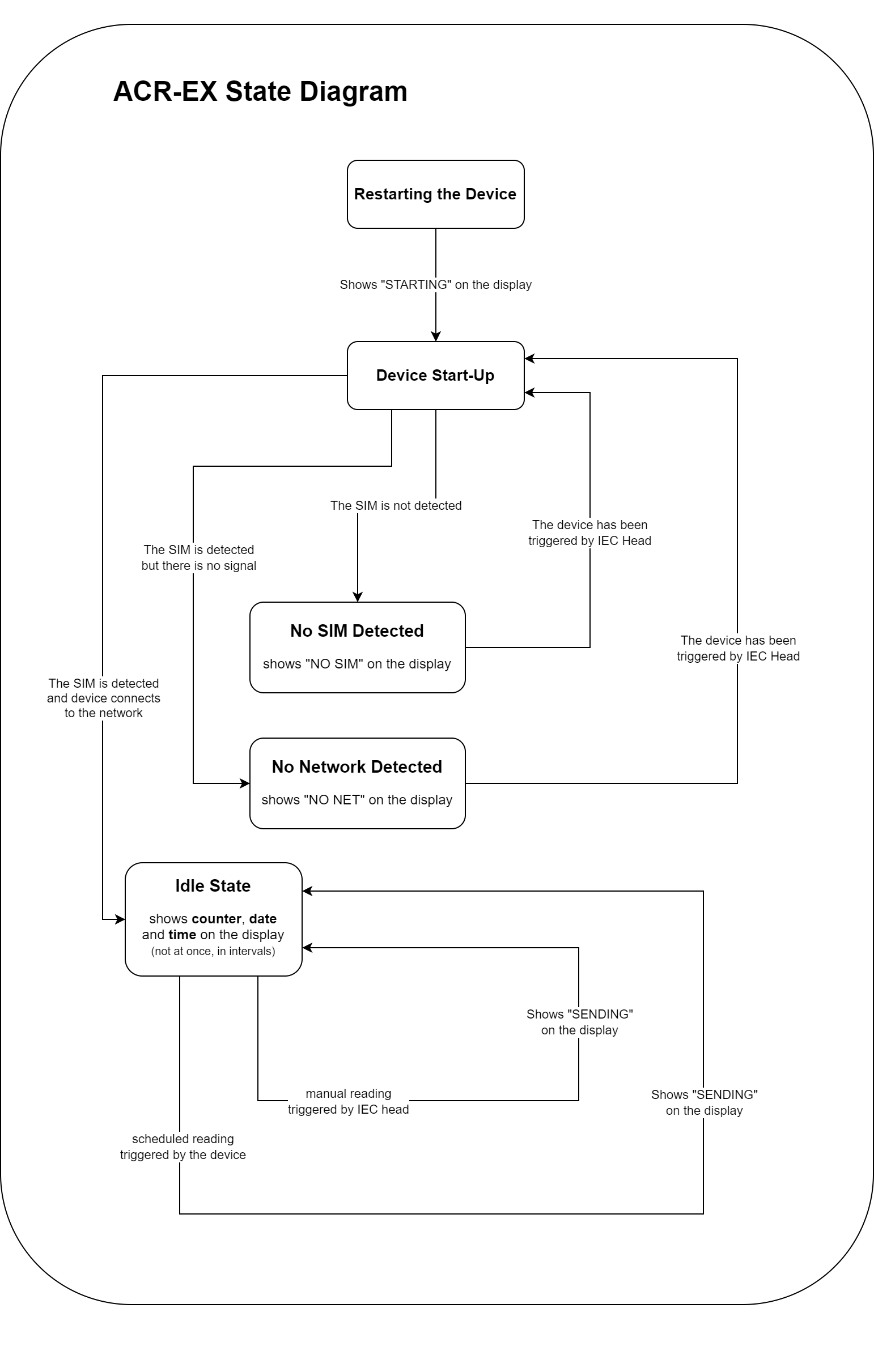
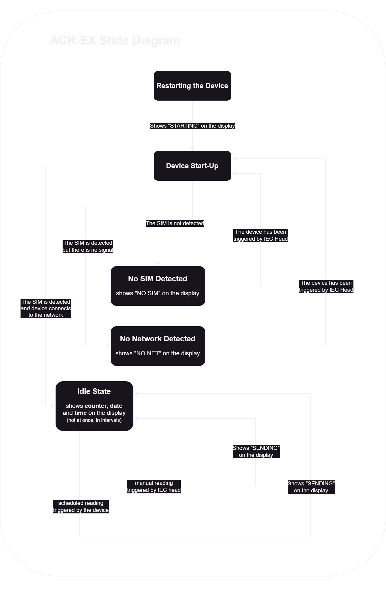
State Diagram - Pulse Counter
This is a state diagram of the pulse counter mode.
The process could be simplified to the following steps:
- The device starts after the restart or when it is plugged in.
- The device checks, whether a SIM card is inserted.
- The device checks, whether a network can be reached.
- The device enters idle state, from which it attempts to send data either at certain intervals, or when manually triggered.
In Text Explanation
- The device can be started either by:
- Plugging in the battery.
- Restarting the device by plugging the battery out, shorting it, and plugging in the battery.
- Either way, the device should display "STARTING" and the show the FW revision.
- The device should now follow these steps:
- The device checks, if a valid SIM card is inserted:
- If there is no valid SIM card, or no SIM card, the display shows "NO SIM" - insert the valid SIM card and tap the magnet on the side.
- If the SIM card is valid, the device then attempts to connect to the network:
- If the device fails to connect, it shows "NO NET" - tap the magnet on the side after it has been resolved (either in configuration or by placing it to a place with a signal).
- The device checks, if a valid SIM card is inserted:
- Once the device successfully connects, it should enter the idle mode.
- From there a scheduled reporting is executed.
- You can also read out the data with help of manual IEC head reading.
- Once the data is sent, the device returns to the idle mode:
- The display shows "SENDING".
Converter Readout (Payload)
| LwM2M Resource | Description | UDP Command Byte (HEX) |
|---|---|---|
| 27165 | Periodic report | 0xA5 |
| 27166 | Periodic report with a Coulomb counter | 0xA6 |
| 27167 | Periodic status report | 0xA7 |
| 27168 | Periodic status report with a serial number | 0xA8 |
| 27170 | Read the archive | 0xAA |
| 27204 | Read the counter | 0xCC |
| 27218 | Read a device info | 0xDA |
| 27221 | Read a ratio | 0xDD |
| 27160 | Ping | 0xA0 |
| 27238 | Signal tester | 0xEE |
| 27239 | Signal tester with a Coulomb counter | 0xEF |
| 27176 | Send a second of the day | 0xB0 |
| 27177 | Send a second of the day - spread | 0xB1 |
| 27178 | Read a display count time | 0xB2 |
| 27179 | Read a display date time | 0xB3 |
| 27180 | Read a maximum detector period | 0xB4 |
| 27181 | Read a sampling period | 0xB5 |
| 27182 | Read the config | 0xB6 |
| 27183 | Read an APN | 0xB7 |
| 27184 | Read an IP | 0xB8 |
| 27185 | Read a port | 0xB9 |
| 27186 | Read a PLMN ID | 0xBA |
| 27187 | Read an ID | 0xBB |
| 27188 | Read mode | 0xBC |
| 27189 | Read UNITSTR | 0xBD |
| 27190 | Read OBIS | 0xBE |
| 27191 | Clear the archive acknowledgment | 0xBF |
| 27224 | CRC16 failed | 0xE0 |
| 27208 | Read a LWM2M endpoint | 0xD0 |
| 27209 | Read a LWM2M server URL | 0xD1 |
| 27210 | Read a LWM2M server port | 0xD2 |
| 27211 | Read a LWM2M local port | 0xD3 |
| 27212 | Read a LWM2M lifetime | 0xD4 |
| 27213 | Read a LWM2M PSK ID | 0xD5 |
| 27214 | Read a LWM2M PSK | 0xD6 |
| 27192 | Read a battery capacity | 0xC0 |
| 27193 | Read a history period length | 0xC1 |
| 27194 | Read a signal tester period | 0xC2 |
| 27195 | Read a signal tester mode | 0xC3 |
| 27196 | Read a signal tester payload length | 0xC4 |
| 27197 | Read a meter ID | 0xC5 |
| 27199 | Read a timezone minutes | 0xC6 |
| 27198 | Read a system time | 0xC7 |
| 27200 | Read an initial baudrate | 0xC8 |
| 27201 | Coulomb Counter reset acknowledgment | 0xC9 |
| 27202 | Read a display decimal places | 0xCA |
| 27203 | Read an extended display enable | 0xCB |
| 27204 | Read an IEC password enable | 0xCE |
Hardware Used
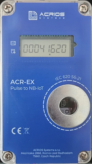
- ACR-EX-100NILCD-I1-C - Display Enabled Pulse to NB-IoT Converter
The converter is designed to retrofit existing meters with pulse output to an NB-IoT communication. The converter is equipped with a pulse input, NB-IoT module, and a display for an easy on-site monitoring.
Hardware Limitations
- Battery life can last up to 15 years, but this may vary significantly due to external factors and natural degradation.
- Pulse input is equipped with a low-pass filter with a cut-off frequency of 7234 Hz.
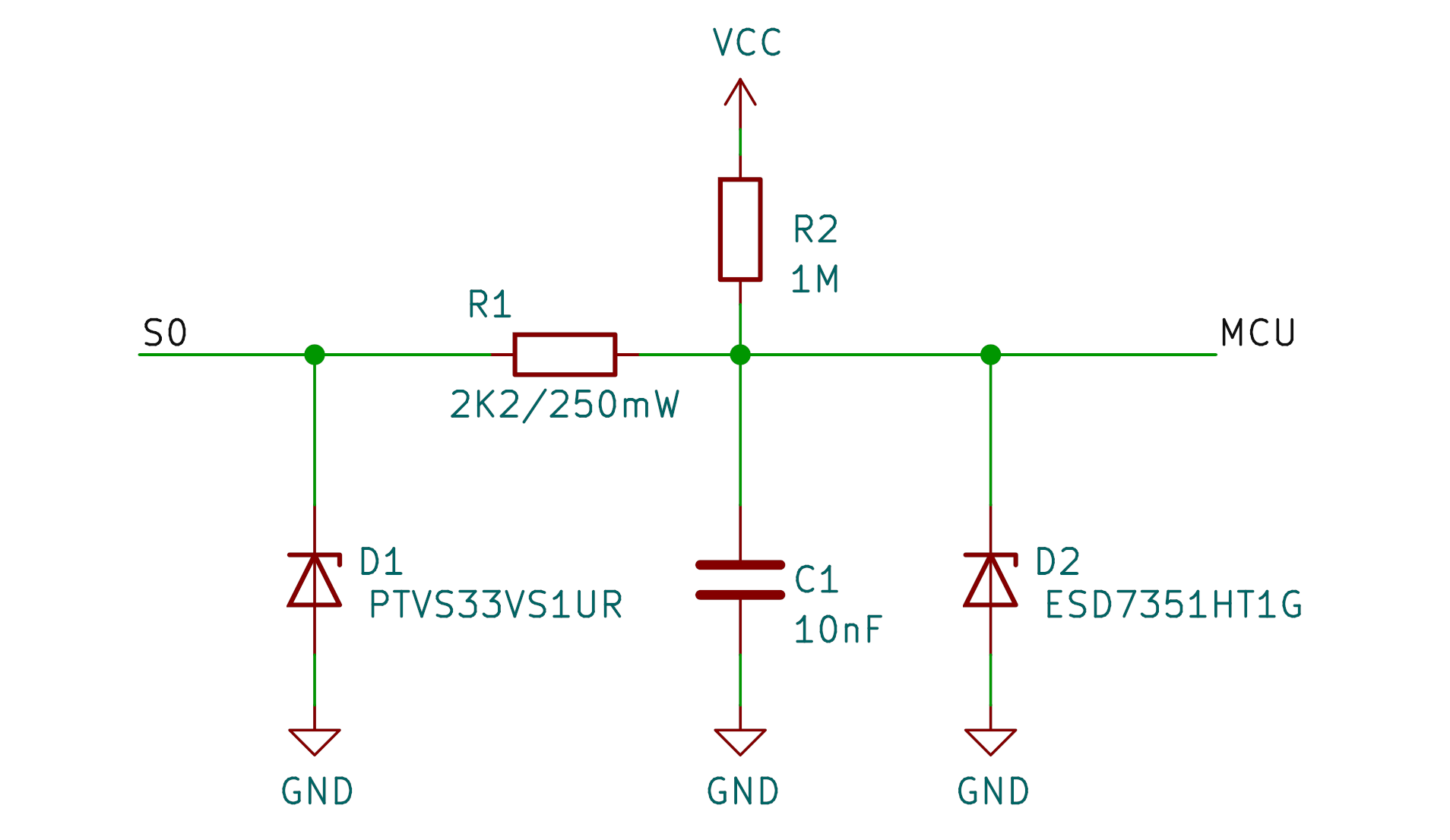
ACR-EX input schematic
Application Limitations
- FW low-pass filter with a cut-off frequency of 50 Hz.
- FW NB-IoT module sent size limitation of 512 bytes.
This means messages larger than 512 B are truncated, with only the initial portion sent, leading to data loss for the remaining content.
Device Management
IoT device management refers to the process of monitoring, configuring, updating, and maintaining IoT devices throughout their lifecycle. It involves various tasks and functionalities aimed at ensuring the reliable and efficient operation of IoT devices deployed in networks. Our device can be managed with the following standards/protocols:
IEC Device Management
IEC 62056-21, formerly known as IEC 1107, is an international standard that specifies the DLMS/COSEM protocol, which stands for Device Language Message Specification (DLMS) and Companion Specification for Energy Metering (COSEM). This protocol is widely used for communication between utilities and various types of energy meters, facilitating efficient data exchange for meter reading, billing, and monitoring purposes. It defines the structure and format of messages exchanged between energy meters and data collection systems, ensuring interoperability and compatibility across different vendors and devices.
Our device is equipped with an optical port compliant with the IEC 62056-21 standard, enabling effortless communication and compatibility.
Optical Probe
An optical probe, often referred to as an optical port or optical head, is a device used for communication with energy meters that support the DLMS/COSEM protocol according to the IEC 62056-21 standard. It typically consists of an optical sensor and associated circuitry housed in a compact unit.
The optical probe is connected to a computer or data collection device via a serial or USB interface. It emits pulses of light that are received by the optical port on the energy meter. These pulses encode data such as meter readings, parameters, or commands and that allows bidirectional communication between the meter and an external device.
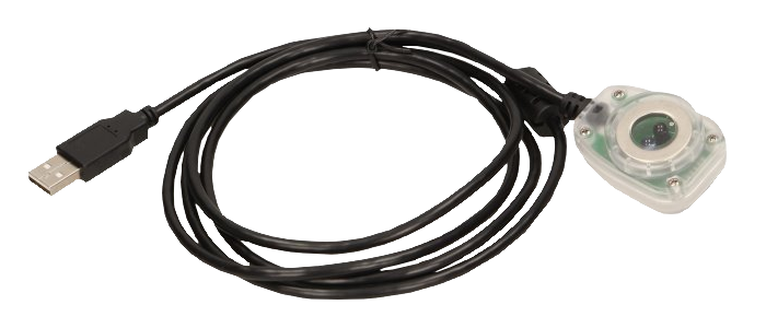
ORNO OR WE 518 optical probe
We also offer ORNO optical probes for the management of our devices (datasheet: EN).
If you wish to order the probes from ACRIOS, use the order code of: Opticka_hlavice_USB-E379
Communication starts at 300 Bd and after sign-on, our device switches to 9600 Bd.
Operation
The device uses C protocol mode and fifth baud speed.
The C protocol mode ensures bidirectional data exchange with baud rate switching and allows data retrieval, programming with increased security, and modes defined by the manufacturer.
The following procedure happens when the device is being used:
- PC sends a request for a transfer of ACR-EX‘s address.
- ACR-EX sends a response with its address. (Sign On)
- PC sends a command for a mode and a baud speed.
Read mode: ACR-EX sends a response containing the archive data.Programming mode: ACR-EX sends a response with an operand for the security algorithm.- PC sends a password (IMEI).
- ACR-EX sends an acknowledgment.
- Communication between the devices ends with the Sign Off command. (Timeout)
Read Mode
Read mode communication diagram
Programming Mode
Programming mode communication diagram
Registers
The device utilizes a range of registers for its IEC interface, facilitating crucial operations and configurations. These registers encompass a diverse set of functionalities, such as:
- Network settings
- Data transmission intervals
- Signal testing parameters
- And others
Registers Description
- IEC_REG_COUNTER - Pulse counter (tracking the number of pulses)
- IEC_REG_IP - Device IP address in IPv4 format
- IEC_REG_PORT - Communication port of the device
- IEC_REG_APN - Access Point Name for mobile network connection
- IEC_REG_PLMNID - Mobile network operator identifier
- IEC_REG_ID - Unique device ID, usually containing the IMEI number
- IEC_REG_RATIO - Conversion ratio used for measurement scaling
- IEC_REG_SIGNAL_TESTER - Device mode selection
- IEC_REG_UNIT - Measurement unit
- IEC_REG_OBIS_CODE - OBIS code used for data identification
- IEC_REG_SEND_DAY_SEC - Time of the day when periodic data sending occurs
- IEC_REG_SEND_DAY_SEC_SPREAD - Spread in seconds for randomized data sending
- IEC_REG_SAMPLING_PERIOD - Data sampling period
- IEC_REG_DISPLAY_COUNT_TIME - Duration for displaying the count value
- IEC_REG_DISPLAY_DATE_TIME - Duration for displaying date and time
- IEC_REG_MAXIMUM_DETECTOR_PERIOD - Maximum period for the detection if min/max flow
- IEC_REG_LWM2M_SERVER_URL - LwM2M server URL or IP address for remote device management
- IEC_REG_LWM2M_SERVER_PORT - LwM2M server port
- IEC_REG_LWM2M_LOCAL_PORT - Local port for LwM2M communication
- IEC_REG_LWM2M_EP - LwM2M endpoint name used for device registration
- IEC_REG_LWM2M_LIFETIME - Lifetime value for LwM2M server registration
- IEC_REG_DEVICE_INFO - Read-only register containing device information
- IEC_REG_LWM2M_PSKID - LwM2M Pre-Shared Key Identity for secure communication
- IEC_REG_LWM2M_PSK - LwM2M Pre-Shared Key for encrypted communication
- IEC_REG_SIG_TESTER_PERIOD - Signal tester interval
- IEC_REG_SIG_TESTER_MODE - Signal tester operating mode
- IEC_REG_SIG_TESTER_PAYLOAD_LEN - Signal tester payload length in bytes
- IEC_REG_BATTERY_CAPACITY - Battery capacity in mAh
- IEC_REG_HISTORY_PERIOD_LEN - Number of days for which historical data is transmitted
- IEC_REG_METERID - Meter ID
- IEC_REG_TZ_MINUTES - Time zone offset in minutes
- IEC_REG_SYSTIME - System time in seconds
- IEC_REG_SEND_PERIODIC_REPORT - Write-only register for triggering manual periodic report sending
- IEC_REG_INIT_BAUDRATE - Initial baud rate setting
- IEC_REG_CC_RESET - Write-only register for performing a coulomb counter reset (battery change)
- IEC_REG_DECIMAL_PLACES - Number of displayed decimal places
- IEC_REG_EXTENDED_DISPLAY - Enables or disables extended display mode
- IEC_REG_PASSWORD_ENABLE - Enables or disables IEC password authentication
- IEC_REG_EXIT - Write-only register used for exiting IEC mode
| Register Name | Address | Length | Operations | Range/Format | Data Type | Default Value |
|---|---|---|---|---|---|---|
| IEC_REG_COUNTER | 0 | 4 | R/W | 0 - 4294967295 | Integer | 0 [count] |
| IEC_REG_IP | 4 | 64 | R/W | IPv4 | String | |
| IEC_REG_PORT | 68 | 4 | R/W | 0 - 65535 | Integer | 4242 |
| IEC_REG_APN | 72 | 64 | R/W | 1 - 63 chars | String | auto |
| IEC_REG_PLMNID | 136 | 4 | R/W | 0 / 00000 - 99999 | Integer | 0 |
| IEC_REG_ID | 140 | 64 | R/W | 1 - 63 chars | String | Device IMEI |
| IEC_REG_RATIO | 204 | 4 | R/W | Ratios | Integer | 1:1 |
| IEC_REG_SIGNAL_TESTER | 208 | 4 | R/W | 0 - 2 | Integer | 0 (Pulse counter UDP) |
| IEC_REG_UNIT | 212 | 16 | R/W | 1 - 15 chars | String | *m3 |
| IEC_REG_OBIS_CODE | 228 | 16 | R/W | nn.nn.nn | String | 3.0.0 |
| IEC_REG_SEND_DAY_SEC | 244 | 4 | R/W | 0 - 86399 | Integer | 21600 |
| IEC_REG_SEND_DAY_SEC_SPREAD | 248 | 4 | R/W | 0 - 86399 | Integer | 0 |
| IEC_REG_SAMPLING_PERIOD | 252 | 4 | R/W | 300 - 86399 | Integer | 3600 |
| IEC_REG_DISPLAY_COUNT_TIME | 256 | 4 | R/W | 3 - 600 | Integer | 20 |
| IEC_REG_DISPLAY_DATE_TIME | 260 | 4 | R/W | 6 - 600 | Integer | 4 |
| IEC_REG_MAXIMUM_DETECTOR_PERIOD | 264 | 4 | R/W | 60 - 86399 | Integer | 300 |
| IEC_REG_LWM2M_SERVER_URL | 268 | 64 | R/W | URL/IP | String | |
| IEC_REG_LWM2M_SERVER_PORT | 332 | 4 | R/W | 0 - 65535 | Integer | 5683 |
| IEC_REG_LWM2M_LOCAL_PORT | 336 | 4 | R/W | 0 - 65535 | Integer | 56833 |
| IEC_REG_LWM2M_EP | 340 | 64 | R/W | 1 - 63 chars | String | acrex |
| IEC_REG_LWM2M_LIFETIME | 404 | 4 | R/W | 86399 - 2678369 | Integer | 30 |
| IEC_REG_DEVICE_INFO | 408 | 128 | R | None | String | Depends on FW and HW |
| IEC_REG_LWM2M_PSKID | 536 | 64 | R/W | 4 - 63 chars | String | "" |
| IEC_REG_LWM2M_PSK | 600 | 64 | R/W | 4 - 63 chars | String | "" |
| IEC_REG_SIG_TESTER_PERIOD | 664 | 4 | R/W | 30 - 86399 | Integer | 900 |
| IEC_REG_SIG_TESTER_MODE | 668 | 4 | R/W | 0 - 2 | Integer | 2 |
| IEC_REG_SIG_TESTER_PAYLOAD_LEN | 672 | 4 | R/W | 64 - 512 | Integer | 512 |
| IEC_REG_BATTERY_CAPACITY | 676 | 4 | R/W | 100 - 20000 | Integer | 8500 [mAh] |
| IEC_REG_HISTORY_PERIOD_LEN | 680 | 4 | R/W | 0 - 3 | Integer | 3 (4 days) |
| IEC_REG_METERID | 684 | 16 | R/W | 1 - 15 chars | String | "" |
| IEC_REG_TZ_MINUTES | 700 | 4 | R/W | -960 - 960 | Integer | 60 |
| IEC_REG_SYSTIME | 704 | 4 | R/W | 0 - 4294967295 | Integer | None |
| IEC_REG_SEND_PERIODIC_REPORT | 708 | 4 | W | 0x00000000 | Integer | None |
| IEC_REG_INIT_BAUDRATE | 712 | 4 | R/W | 0, 1 | Integer | 0 (300 Baud) |
| IEC_REG_CC_RESET | 716 | 4 | W | 0x00000000 | Integer | None |
| IEC_REG_DECIMAL_PLACES | 720 | 4 | R/W | 0 - 8 | Integer | 3 (0.001) |
| IEC_REG_EXTENDED_DISPLAY | 724 | 4 | R/W | 0, 1 | Integer | 0 (Disabled) |
| IEC_REG_PASSWORD_ENABLE | 728 | 4 | R/W | 0, 1 | Integer | 0 (Disabled) |
| IEC_REG_SENDING_PERIOD | 732 | 4 | R/W | 0 - 86400 | Integer | 86400 [s] (Once a day) |
| IEC_REG_EXIT | 65530 | None | W | None | None |
n - number from 0 to 9
Different color coding represents different categories: Common registers, common Counter registers for UDP and LwM2M modes, LwM2M mode registers and Signal Tester mode registers.
Ratios
| Ratio | Integer |
|---|---|
| 1000000:1 | 1000000 |
| 100000:1 | 100000 |
| 10000:1 | 10000 |
| 1000:1 | 1000 |
| 100:1 | 100 |
| 10:1 | 10 |
| 1:1 | 1 |
| 1:10 | -10 |
| 1:100 | -100 |
| 1:1000 | -1000 |
| 1:10000 | -10000 |
| 1:100000 | -100000 |
| 1:1000000 | -1000000 |
Converter Modes
0: Pulse counter UDP1: Signal Tester2: Pulse counter LwM2M
History Period Length
0: Only transmits newly collected samples from the past 24 hours.1, 2, 3: Transmits samples from the last day along with an additional history of 1, 2, or 3 preceding days, respectively.
The number of samples transmitted is determined by the sampling rate. The internal buffer capacity is limited to 128 samples. If the number of accumulated samples exceeds this limit, the oldest samples will be overwritten by newer ones, resulting in data loss.
Initial Baudrate
0: 300 Baud (with switching to 9600 Baud after sign-on)1: 9600 Baud
Displaying Decimals
The device supports displaying values with decimal precision, depending on the ratio setting.
0: No decimals (1 )1: 1 decimal place (1.2 )2: 2 decimal places (1.23 )- etc.
Decimals are only displayed if the configured ratio is less than 1 (e.g., 1:10, 1:100, etc.). If the ratio is 1:1 or greater, the value will be shown as a number of pulses multiplied by ratio.
Example with a ratio of 1:100 and 3 decimal places:
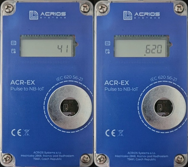
Extended Display
The extended display mode allows switching between whole values and decimal values (for displaying greater numbers).
0: Disabled1: Enabled
The decimal part is only displayed if the configured ratio is less than 1 (e.g., 1:10, 1:100, etc.). If the ratio is 1:1 or greater, the value will be shown as a number of pulses multiplied by ratio.
Example with the extended display enabled, ratio of 1:100, and 3 decimal places:
IEC Password Authentication
By default, password authentication is Disabled on the device, allowing a simplified authentication flow using the device IMEI. However, when authentication is enabled, only the visible key (VKEY) from the device info register is accepted.
-
0: Disabled -
1: Enabled -
During sign-on, the device sends its IMEI as the device ID.
-
In default mode, the device accepts either the IMEI or VKEY as the password.
-
If authentication is enabled, the device only accepts the VKEY, rejecting IMEI-based authentication.
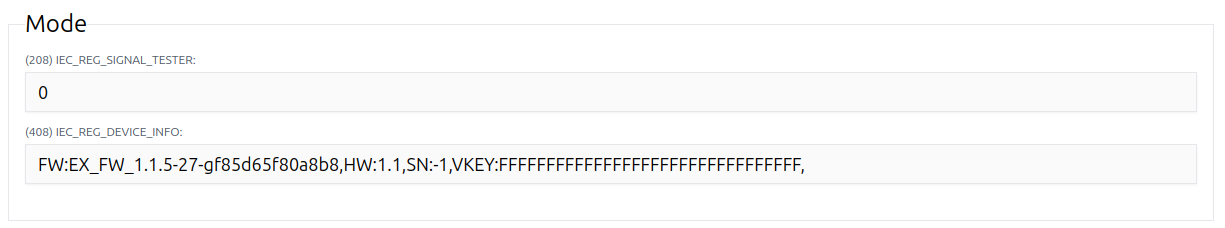
SN:-1 and VKEY:FFFFFFFFFFFFFFFFFFFFFFFFFFFFFFFF are placeholders used in development units. In production units, these values are unique.
Managing Devices
Please refer to ACR-EX GUI tool manual for detailed instructions on how to manage the device via the IEC interface.
LwM2M Device Management
LwM2M is a lightweight and efficient device management protocol designed for IoT devices. It provides a standardized way to manage and monitor IoT devices remotely, enabling a secure and reliable communication between devices and servers. LwM2M is based on the CoAP (Constrained Application Protocol) and uses the OMA (Open Mobile Alliance) LwM2M object model to define the structure and attributes of IoT devices.
Our device uses SIMCOM SIM7022 module for communication which supports the LwM2M protocol.
Data
In LwM2M protocol, objects and resources are fundamental concepts that represent the structure and attributes of IoT devices and their capabilities.
Objects
Objects represent logical groupings of related resources that define the functionality or capabilities of IoT devices. Each object is identified by a unique Object ID, which is a numerical value assigned to it within the LwM2M specification. Objects encapsulate properties, behaviors, and metadata associated with a particular aspect of a device functionality, such as:
- Device information
- Connectivity
- Sensors
- Actuators
- Firmware management
- And others
Resources
Resources are individual data elements or attributes within an object that represent specific properties, states, or capabilities of an IoT device. Each resource is identified by a unique Resource ID within its parent object and is accessed using a combination of an Object ID and a Resource ID.
Resources can be of different types, such as integer, float, string, boolean, opaque, etc., depending on the type of data they represent. Resources may have associated operations or functionalities, such as read, write, execute, or observe, which define how they can be accessed, modified, or monitored.
Data Operations
LwM2M protocol facilitates various data operations for managing and interacting with IoT devices. These operations include read, write, execute, and observe, which allow clients and servers to access, modify, execute, and monitor the data and resources of IoT devices remotely.
Read
Reading data from resources on IoT devices allows retrieving information such as sensor readings, device status, or configuration parameters. Clients can send read requests for specific resources using LwM2M protocols, and devices respond with the requested data.
Write
Writing data to resources enables configuring device settings, updating parameters, or sending commands to IoT devices. Clients can send write requests to modify resource values, and devices acknowledge the changes accordingly.
Execute
Executing commands or actions on IoT devices triggers specific behaviors or operations. Clients can invoke execute requests on executable resources, prompting devices to perform tasks such as resetting, rebooting, or initiating actions based on the request.
Observe
Observing resources enables continuous monitoring of data changes or events on IoT devices. Clients can establish observation relationships with specific resources, and devices notify clients about updates or modifications to the observed data in real-time.
Server
To use LwM2M, you need to set up the server and connect it to the device. The server is responsible for managing device registrations, data communication, firmware updates, and device monitoring. The server can be a cloud-based platform, an on-premises server, or a dedicated LwM2M server. You could use an open-source LwM2M server such as Leshan or a commercial LwM2M platform such as Coiote.
Adding a New Device to the Server
To add a new device to the LwM2M server, you need to register the device with the server by providing the necessary device information, such as the endpoint name and security credentials.
Leshan
For comprehensive setup instructions, refer to the official documentation: Getting Started with Leshan
Leshan supports the following security modes:
- PSK (Pre-shared key)
- RPK (Raw public-key)
- X.509 (Certificate)
- NoSec (No security)
To add a device to a Leshan server, you'll need to configure its endpoint and security mode. If you opt for modes other than "NoSec", identity and key parameters are required for authentication. This ensures a secure and seamless integration of devices into the Leshan ecosystem.
Coiote
Setting up Coiote is straightforward and user-friendly. It's basically signing up for an account and choosing the desired pricing plan.
Coiote supports the following security modes:
- PSK (Pre-shared key)
- NoSec (No security)
To add a device to a Coiote server, you'll need to configure its endpoint and security mode. If you opt for PSK, you'll need to provide a key identity and a key for authentication. The key format can be HEX or plain text. Coiote has a custom name option for better identification.
Client
We use our own C-based LwM2M client for streamlined performance and customized functionality. This tailored solution ensures efficient management of IoT devices to meet our specific needs.
First Time Client Setup
To use LwM2M, you need to set up the device and connect it to the server. The initial setting of the device can be done manually using an optical probe or by us during the production if you provided us with the parameters.
Necessary parameters:
- Server address (URL/IP)
- Bootstrap server
- Server port (5683/5684 - secure)
- Security mode (PSK)
- Pre-shared key
- Connection type (IPV4/IPV6)
- Local port
- Endpoint name
- Binding mode
- Lifetime
In the absence of a security mode and pre-shared key settings, the device will default to a non-secure mode.
ACR-EX Custom LwM2M Objects and Resources
Our device uses custom LwM2M objects and resources to represent its functionality and capabilities. Custom objects and resources in LwM2M offer the flexibility to tailor the device management to specific use cases and requirements.
These objects and resources are defined according to the OMA LwM2M object model and provide a structured representation of the device's properties, states, and behaviors.
By defining custom objects and resources, developers can extend the standard functionality of LwM2M to accommodate unique device features and data points.
Such customization empowers users to efficiently manage diverse IoT devices and extract meaningful insights from their data, enhancing overall system performance and functionality.
Our resource IDs are generated by adding the decimal representation of a hexadecimal command byte to the offset of 27000. For example, the resource ID for the command byte 0xA5 is 27000 + 165 = 27165. You can find the calculated command byte values in the LwM2M resource column of the Uplink command bytes table.
ACR-EX Connection Configuration (Object ID 32769)
| Resource ID | Name | Type | Unit | Operations |
|---|---|---|---|---|
| 27183 | APN | String | - | R/W |
| 27184 | IP | String | - | R/W |
| 27185 | Port | String | - | R/W |
| 27186 | PLMNID | String | - | R/W |
| 27187 | ID | String | - | R/W |
| 27213 | LWM2MPSKID | String | - | R/W |
| 27214 | LWM2MPSK | String | - | R/W |
| 27208 | LWM2MEndpoint | String | - | R/W |
| 27209 | LWM2MServerURL | String | - | R/W |
| 27210 | LWM2MServerPort | String | - | R/W |
| 27211 | LWM2MLocalPort | String | - | R/W |
| 27212 | LWM2MLifetime | String | - | R/W |
ACR-EX Device Configuration (Object ID 32770)
| Resource ID | Name | Type | Unit | Operations |
|---|---|---|---|---|
| 27000 | DeviceReset | String | - | E |
| 27189 | UnitStr | String | - | R/W |
| 27190 | ObisCode | String | - | R/W |
| 27221 | Ratio | String | - | R/W |
| 27188 | Mode | String | - | R/W |
| 27178 | DisplayCountTime | String | - | R/W |
| 27179 | DisplayDateTime | String | - | R/W |
| 27180 | MaximumDetectorPeriod | String | - | R/W |
| 27181 | SamplingPeriod | String | - | R/W |
| 27176 | SendSecondOfDay | String | - | R/W |
| 27177 | SendSecondOfDaySpread | String | - | R/W |
ACR-EX Gas Meter (ID 3277X)
| Resource ID | Name | Type | Unit | Operations |
|---|
Note that this feature is currently under development.
Calculations
Timestamp
uint32_t getTimeStampNow(uint8_t* buffer)
{
extern volatile uint32_t year;
extern volatile uint32_t month;
extern volatile uint32_t day;
extern volatile uint32_t hour;
extern volatile uint32_t minute;
extern volatile uint32_t second;
time_t timestamp;
struct tm currTime;
currTime.tm_year = year - 1900;
currTime.tm_mday = day;
currTime.tm_mon = month - 1;
currTime.tm_hour = hour;
currTime.tm_min = minute;
currTime.tm_sec = second;
timestamp = mktime(&currTime);
timestamp -= 1199145600; // Subtract 1.1.2008 epoch offset
if(buffer)
{
memcpy(buffer, ×tamp, 4);
}
return (uint32_t) timestamp;
}
The getTimeStampNow function calculates the timestamp based on the current date and time, measuring time from January 1, 2008, in UTC.
The year, month, day, hour, minute, and second variables are updated by the device's NB-IoT module. The getTimeStampNow function calculates the timestamp based on the current date and time.
Min/Max flow rate
Min flow rate is initialized to the maximum possible value of 64 byte integer, and max flow rate is initialized to the zero.
If calculated flow rate is less than the min flow rate, the min flow rate is updated with the calculated flow rate. If calculated flow rate is greater than the max flow rate, the max flow rate is updated with the calculated flow rate.
- Multiplication by 1,000,000: This scaling factor ensures that the flow rate calculation results in whole numbers rather than fractions.
- Timestamp Difference: The difference between the two timestamps represents the interval between pulse count checks. This interval is crucial for calculating the rate of change accurately.
- Pulse-to-Unit Ratio: The pulse-to-unit ratio is used to convert the pulse count to the desired unit of measurement. This ratio is set by user and is used by backend parser to convert the flow rate to the appropriate unit.
Example calculation of flow rate
This number is send to backend and parsed with the ratio to get the flow rate in the desired unit. If the ratio is 1000:1, the flow rate is calculated as follows:
Troubleshooting & FAQ
The device is not connecting to the GUI
- Please, make sure to use a Chromium based browser, we strongly recommend to use Google Chrome (other Chromium based browsers still may cause unexpected issues). Make also sure that the serial line is not opened on any other serial line monitor.