Pulse to NB-IoT Converter
Integration manual for the pulse to ACRIOS Systems converters ACR-CV-101N-I4-D and ACR-CV-101N-I4-EAC.
Introduction
The following article contains the documentation needed for the ACRIOS Systems Pulse to NB-IoT converter. The documentation refers to the default Lua script and covers the following topics:
- The typical use of the technology
- The nature of the techonology
- Overview of the hardware used and its limitations
- Overwiew of the application possibilities of the device
- Configuration of the device with help of Lua script
- Basic troubleshooting and FAQ
Typical Use-Case
The integration of a pulse to NB-IoT converter offers a robust solution for efficiently monitoring and managing various types of utility meters, such as electric meters or gas meters. This technology enables real-time data collection and transmission, facilitating enhanced operational efficiency and informed decision-making.
Scenario:
Consider an electric utility company responsible for providing electricity to a large urban area. This utility company needs to monitor electricity usage across thousands of residential and commercial properties. Traditional methods of manual meter reading are time-consuming, prone to errors, and lack the capability for real-time monitoring. The challenge is to implement an efficient, reliable, and scalable system for automatic meter reading (AMR) and data transmission to the central management system.
Solution:
The pulse to NB-IoT converter provides a plug-and-play solution to address this challenge. By retrofitting existing meters with pulse output to the converter, the utility company can seamlessly integrate the meters into the NB-IoT network. This enables the utility company to monitor electricity consumption in real-time, generate accurate billing, and optimize energy distribution.
Benefits:
- Time and Cost Savings: The quick installation process eliminates extensive configuration and wiring efforts, reducing installation time and associated costs.
- Seamless Integration: The plug-and-play nature of the solution simplifies the integration of heat meters into the district heating network, minimizing disruption to the residents.
- Reliable Communication: The external antenna ensures reliable signal propagation, maintaining consistent communication even in complex urban environments.
- Real-time Insights: The solution provides real-time heat consumption data, enabling accurate billing and informed decision-making for energy optimization.
- Enhanced Data Accuracy: The conversion of pulse signals to digital data minimizes the risk of data discrepancies, leading to more accurate billing and usage analytics.
- Long Battery Life: The NB-IoT modules are designed for low power consumption, ensuring long battery life for the converters and reducing maintenance frequency.
- Secure Communication: NB-IoT offers robust security features to protect data integrity and prevent unauthorized access, ensuring secure communication between the meters and the central management system.
What Is a Pulse Output?
A pulse output signal is a common method used by various utility meters, such as electric, water, and gas meters, to indicate consumption levels.
This method works by assigning each pulse to a specific quantity of energy, water, or gas. For example, one pulse might represent 100 liters of water, 10 cubic meters of natural gas, or 1000 watts of electricity. Thus, for every 1000 watts that pass through your electric meter, one pulse is generated. The pulses are counted over time to calculate the total consumption.
Modern meters often use pulses at smaller measurement quantities to provide more detailed data. Pulse output meters are advantageous for interoperability, as they can be read by multiple vendors' systems, rather than being restricted to the meter's original vendor.
Pulse output is a reliable and efficient method for measuring and transmitting consumption data, playing a crucial role in modern utility management and automated meter reading systems.
Converter Integration
Functions
- Configurable number of used channels (default amount: 4)
- Configurable sampling period interval (default interval: 15 minutes)
- Configurable aggregation ratio for sending data (default: 4x15 minutes -> 1 hour)
- Configurable receive timeout duration, (default duration: 15 seconds [15,000 ms])
- Configurable communication watchdog interval for reset, (default interval: 1 day)
- Configurable history length for data transmission, (default length: 2)
- Configurable IP address of the server or backend
- Configurable port number for communication
- Configurable protocol for communication : UDP or TCP (default protocol: UDP)
Out of the Box Behaviors
Once a meter is connected to the converter, the converter will by default start counting pulses and sending data to the server. The converter will send data every hour, and the data will be aggregated every 15 minutes.
Converter Readout (Payload)
The readout from the converter is sent in a form of binary payload.
This is a payload example using default Lua script parameters
Raw payload from serial port:
00 : 03 00 00 00 04 0F 04 02 E6 0D 21 00 00 00 20 00
10 : 00 00 1E 00 00 00 1C 00 00 00 1C 00 00 00 1B 00
20 : 00 00 1A 00 00 00 19 00 00 00 24 00 00 00 23 00
30 : 00 00 22 00 00 00 1E 00 00 00 1E 00 00 00 0E 00
40 : 00 00 0B 00 00 00 08 00 00 00 15 00 00 00 14 00
50 : 00 00 13 00 00 00 12 00 00 00 12 00 00 00 10 00
60 : 00 00 0B 00 00 00 09 00 00 00 19 00 00 00 18 00
70 : 00 00 17 00 00 00 16 00 00 00 16 00 00 00 10 00
80 : 00 00 0B 00 00 00 08 00 00 00
Reformated Payload for Better Readability:
A visual representation of what different parts of the payload represent:
- Parameters are indicated by the color red and have a fixed length of 10B
- 1st channel, 2nd channel, 3rd channel and 4th channel are indicated by their respective colors
03 00 00 00 04 0F 04 02 E6 0D
21 00 00 00 20 00 00 00 1E 00 00 00 1C 00 00 00

1C 00 00 00 1B 00 00 00 1A 00 00 00 19 00 00 00
24 00 00 00 23 00 00 00 22 00 00 00 1E 00 00 00

1E 00 00 00 0E 00 00 00 0B 00 00 00 08 00 00 00
15 00 00 00 14 00 00 00 13 00 00 00 12 00 00 00

12 00 00 00 10 00 00 00 0B 00 00 00 09 00 00 00
19 00 00 00 18 00 00 00 17 00 00 00 16 00 00 00

16 00 00 00 10 00 00 00 0B 00 00 00 08 00 00 00
Parameters:
A visual representation of what different bytes in Parameters mean. Different colors once again represent their respective contents.
03 00 00 00 04 0F 04 02 E6 0D- Frame counter [4B] -
03 00 00 00= 3 frames - Channels count [1B] -
04= 4 channels - Sampling period [1B] -
0F= 15 minutes - Aggregation ratio [1B] -
04= 1:4 (4x15 minutes = 1 hour) - History length [1B] -
02= 2 hours (2x1 hour = 2 hours) - Battery voltage [2B] -
0D E6= 3558 mV
Channel:
A visual representation of what different bytes in a Channel mean. Different colors once again represent their respective contents.
21 00 00 00 20 00 00 00 1E 00 00 00 1C 00 00 00
1C 00 00 00 1B 00 00 00 1A 00 00 00 19 00 00 00- Pulse count [4B] -
21 00 00 00= 33 - Pulses aggregation [16B] (including pulse count)
- Pulses history [32B] (including pulses aggregation)
Hardware Used
- ACR-CV-101N-I4-D - Pulse Counter to NB-IoT Converter, battery powered
- ACR-CV-101N-I4-EAC - Pulse Counter to NB-IoT Converter, externally powered
The converter allows you to connect any meter or other device equipped with a pulse output. The converter is designed to convert the pulse output to NB-IoT communication.
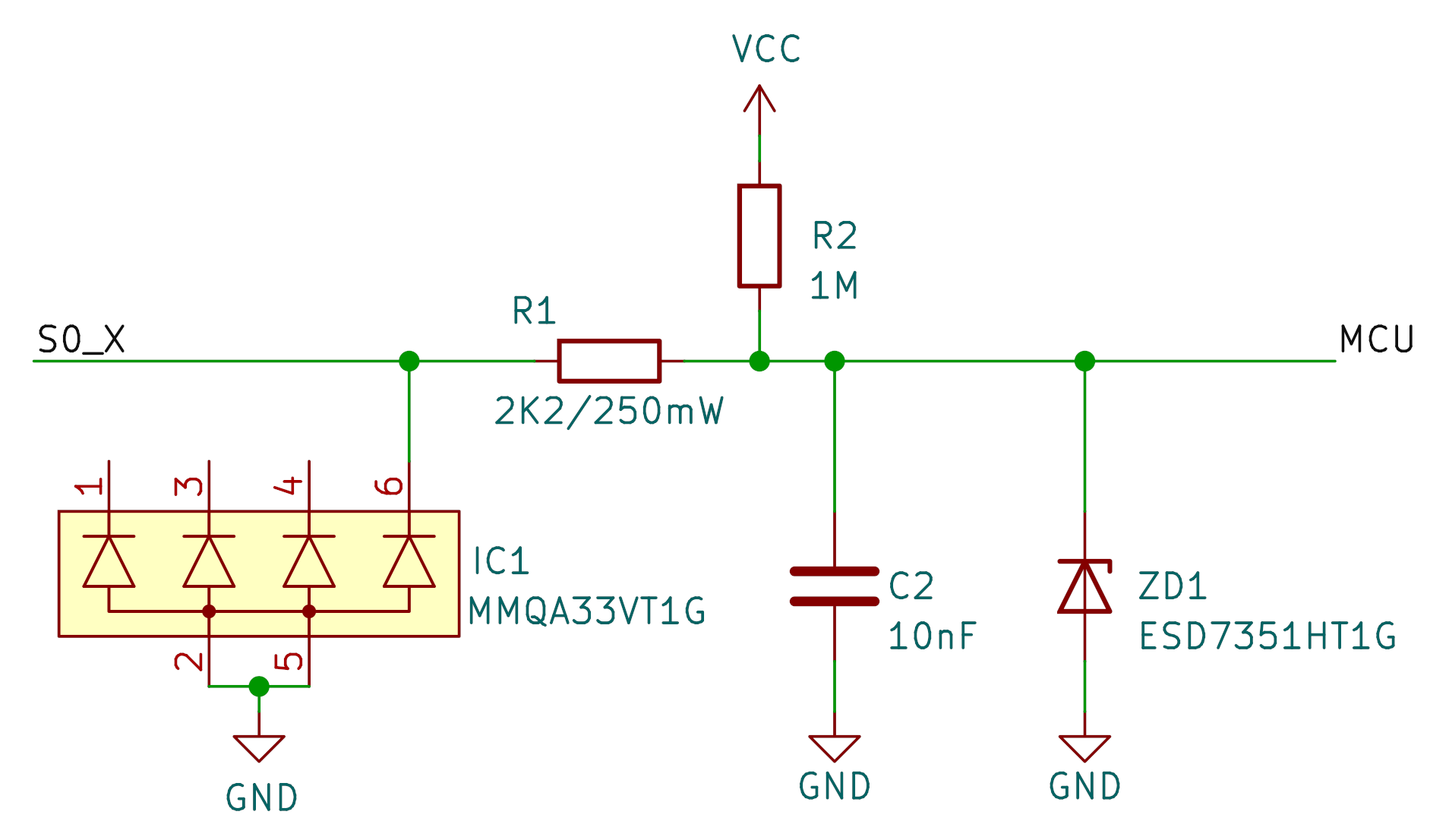
Hardware Limitations
- The hardware allows you to connect only up to 4 pulse outputs.
- The battery lifetime is limited.
- Every pulse input is equipped with a low-pass filter with a cut-off frequency of 7234 Hz.
Application Limitations
- FW low-pass filter with cut-off frequency of 50 Hz.
- Limited Storage Capacity of 4096 bytes.
- FW NB-IoT module sent size limitation of 512 bytes (messages larger than that are truncated, with only the initial portion sent, leading to data loss for the remaining content).
Lua Script Configuration
Lua scripting language is used to configure our devices. It is an effective tool for dynamic device customization, easy to use but also fit for advanced users, who would like to fully configure their devices.
Here you can access the default script for our Pulse Counter to NB-IoT Converter.
For script configuration, please use Acrios GUI.
Main Parts of the Script
Configuration
Below you can see what following attributes can be configured in the Lua script.
---- CONFIGURATION ----
------- NB-IoT --------

APN = "auto"            -- "auto" is autodetection per SIM, use "nb.m2mc" for Miotiq
PLMNID = "0"            -- 0 is autodetection per SIM, use 23003 for Vodafone CZ explicit settings

ip = "192.168.0.20"
port = 4242
protocol = "UDP"            -- UDP or TCP
receiveTimeout = 15000      -- the maximum execution time in milliseconds

-- No communication watchdog
-- Reset if no downlink message is received from the server/backend at least once per specified time
noComWdg = 24*3600*1000    -- 1 day

------ Timing ---------
--- wakeup interval ---
usedChannels = 4
samplingPeriodMinutes = 15
aggregationRatio = 4 -- 4 <=> 1h sendingPeriod
historyLength = 2 -- multiply the number of samples by 2 (including historical data)
-----------------------
Troubleshooting & FAQ
The device is not connecting to the Network Server
- Please check if the inserted keys are correct, make sure the device is configured in OTAA and that the AppEUI is not required. In case AppEUI is required, please use the same “0” - 00 00 00 00 00 00 00 00 00 00 00 00 00 00 00 00.
The device is not connecting to the GUI
- Please, make sure to use a Chromium based browser, we strongly recommend to use Google Chrome (other Chromium based browsers still may cause unexpected issues). Make also sure that the serial line is not opened on any other serial line monitor.
The device has connected, the Lua script was uploaded but it is not possible to connect anymore
- Make sure the battery has been disconnected for a longer period of time to discharge the capacitor or alternatively short the battery pins on the PCB. Connect the two metal pins in the battery connector on the PCB with something conductive (tip of screw driver, paper clip, tip of a pen etc.). The device can connect only when in bootloader or when it is sleeping. If the device is in the application Lua script and currently running, it will not connect.
Where do I configure the LUA script?
- At gui.acrios.com, please make sure to use Chromium based browser, we strongly recommend to use Google Chrome.
Where can I see a data or serial line log?
- You can check any serial line monitor such as PuTTy or Termite. Please, make sure the serial line monitor configuration is - baud rate: 115 200, data bits: 8, stop bits: 1, parity: none.
I want to have a possibility to remotely configure the hardware and the Lua script. How can I do it?
- You can either take a look at our documentation that is available at wiki.acrios.com and modify the Lua script by yourself or you can contact our support at support@acrios.com which should point you towards the right solution.